Installation Instruction VARIODYN
®
D1 System
FB 798663.GB0 / 05.19 25
6 Devices
Digital-Output-Module (DOM)
The DOM (Part No. 583361.22 or 583362.22) is the central control element of the VARIODYN
®
D1 System.
Components such as the call stations, the double final amplifiers, and also the loudspeakers are connected to a
DOM. A DOM offers interfaces to all input/output modules and also manages and monitors the loudspeaker
circuits. Up to 250 DOM can be connected via the Ethernet connection to allow realisation of small to large VAS.
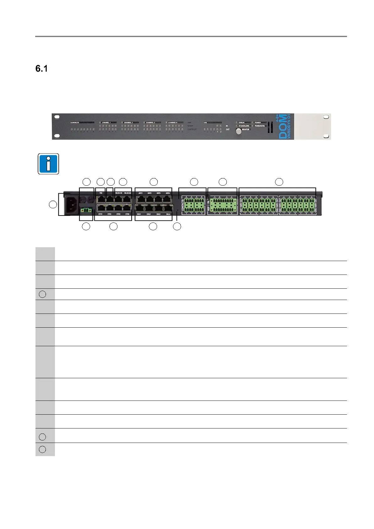
Fig. 18: Front view (the DOM4-24 is shown here)
Additional information on LED indicators and buttons can be found in the operating instructions
(Part No. 798662.GB0).
1
2
3
4
5
7
6
11
8
9
10
3.1
12
+ 24 V -
1,5AT
5AT
Fig. 19: Rear view Digital Output Module (DOM)
110 … 230 V AC nominal voltage via IEC power socket
Device fuses F1 and F2
Two wire interface (TWI), e.g. for connection of a time synchronisation module (TCM)
Do not connect!
2 x RJ45-plug connections AF output to power amplifier (PA)
AVC1 to AVC4 - 4 x inputs for automatic volume control (AVC)
Connection terminals of the eight potential-free control contacts
(switching capacity max. 30 V AC / 1 A or 30 V DC / 1 A)
Plug connection to the output of the power amplifier (prefabricated system cable available).
The terminals of the SPK-outputs are designed with touch protection
• Four power amplifier inputs (PA)
• Four power amplifier backup inputs (REP)
Connection of the loudspeaker circuits
• DOM4-8: 4 channels, each with 2 circuit relays
• DOM4-24: 4 channels, each with 6 circuit relays
Do not activate button – for internal use und service only
DAL1 to DAL4 - 4 x RJ45-plug connections DAL bus / device
ETH1 to ETH4 - 4 x RJ45-plug connections Ethernet network 100 Mbit/s with switch function
24 V DC Emergency power supply (if available)
 Loading...
