Installation Instruction VARIODYN
®
D1 System
FB 798663.GB0 / 05.19 63
Power Amplifiers 4XD-Series
The power amplifiers provide four independent amplifier channels (double final amplifiers). The described
functions depend on the amplifiers required and/or used for the specific building.
For additional information refer to product catalog.
7.4.1 Power Amplifier 4XD125B
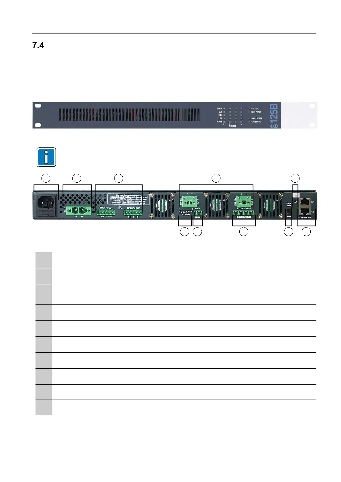
Fig. 54: Front view of power amplifier 4XD125B
Additional information on LED indicators refer to operating instruction (Part No. 798662.GB0).
Fig. 55: Rear view of power amplifier 4XD125)
230 V AC rated voltage via IEC power socket and primary fuse T 8 A / 250 V
24 V DC emergency power supply
Plug connections to control unit (use system cable).
The SPK outputs are designed with touch-protected terminals.
2 x output 24 V external
PE connection 0 V and housing
Plug connection – AF input signal from the control unit
GAIN LOW / MAX
EXTENSION L/F
BATT / TEMP – Temperature sensor
CONFIG - DIP-Switch
 Loading...