Installation Instruction VARIODYN
®
D1 System
FB 798663.GB0 / 05.19 39
View-Control-Module (VCM)
The View Control Module (Part No. 583351) allows the standard-compliant display of collective messages as well
as operation via the five integrated buttons. For VAS according to EN 54-16, at least one VCM required. For every
additional room with VAS installation cabinets, a separate VCM must be used.
The module is connected to a Universal Interface Module (UIM) and supplied with 24 V DC via the emergency
power supply. The first contact of DOM 1 must be connected to one of the VCM inputs for monitoring of the life
sign signal of the DOM.
The VCM is configured via the programming and service software Designer D1.
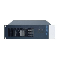
Fig. 33: Front view of View-Control-Module (VCM)
Additional information on the indicators refer to operating instructions (Part No. 798662.GB0).
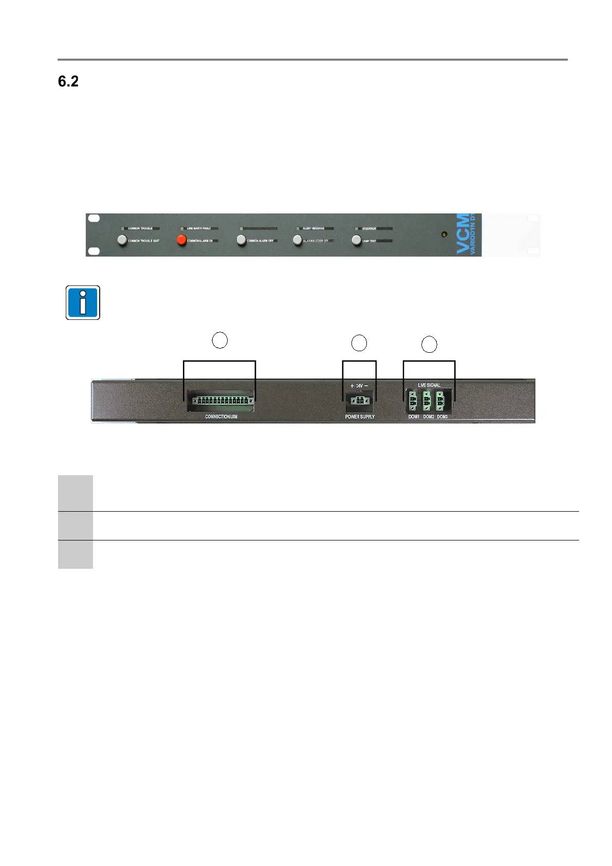
Fig. 34: back view of View-Control-Module (VCM)
Plug-in connection for connecting the control contacts of the UIM.
The terminals are designed with touch protection.
24 V DC power supply
3 inputs for monitoring the DOM life sign signals.
 Loading...