Installation Instruction VARIODYN
®
D1 System
FB 798663.GB0 / 05.19 83
8.3.1 Connecting the emergency power supply (Part No. 581722 / -23 / -24 / -25)
The emergency power supply units are designed to connect the components of a voice alarm system. The
amplifier outputs are equipped with a 30 A fuse.
Higher power amplifiers that require a higher current should be connected to two outputs simultaneously
(2 x 30 A).
Connectors for connecting the outputs are included with the power supply unit. The maximum cable diameter is:
• 6 mm
2
for the amplifier outputs
• 2.5 mm
2
for the 24 V control unit outputs
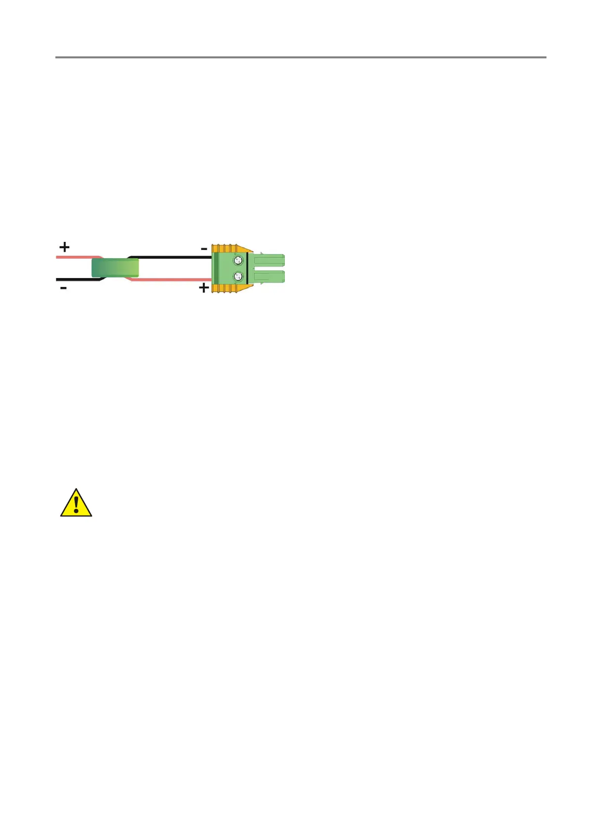
For emergency power inputs of the amplifiers > 45 μF, use the included toroidal ferrite core as illustrated below.
Fig. 77: Using the ferrite core
Emergency power supply PSU 24V-2 has two outputs and emergency power supply PSU 24V-4 has four
outputs for control units of the voice alarm system. If multiple control units and peripherals are required, multiple
control units can be connected to one of these outputs. The use of a separate fuse to protect each strand is
recommended.
Connecting the batteries
The power supply unit does not include dedicated fuses for the batteries.
If such fuses are required, they should be installed close to the positive pole of a battery, separately for each
strand.
Use cable (maximum diameter 16 mm
2
) to connect the batteries to the emergency power supply terminals
labelled BAT. Observe polarity.
Incorrect connection of the batteries can seriously damage the emergency power supply and
connected peripherals.
The positive poles of the terminals are labelled with numbers to permit differentiation of the battery strands. Each
strand is monitored separately. The minus poles are connected to one another.
Use 0.75 mm
2
cable to connect the M outputs in the centre of the respective row of batteries. Install a 0.5 to 2 AF
fuse close to the batteries to protect this connection.
Connecting the temperature sensor
Connect the external temperature sensor (included with the delivery) to the dedicated socket
(Temp sensor / TEMP FÜHL). The temperature sensor should be positioned close to the batteries, ideally
between neighbouring batteries.
 Loading...