Installation Instruction VARIODYN
®
D1 System
82 FB 798663.GB0 / 05.19
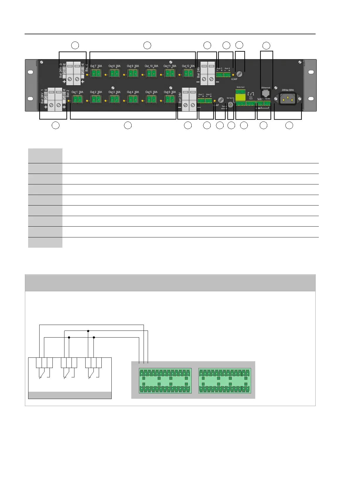
Fig. 76: Rear view
Connecting terminals (+ / -) for up to two 24 V batteries (
BAT1, BAT2, BAT3, BAT4)
and four
additional ports for charging the battery (M)
Connecting terminals for up to twelve power amplifiers (24 V / 40 A)
Connecting terminals for four control units, up to three DOM4-8 or 4-24 (24 V / 5 A) per connection
Fuse 6.3 AF
Ethernet port (Part No. 581725 only)
Female appliance connector for 230 V AC nominal voltage
Two inputs for external error messages (EXT FLT1 / EXT FEHL 1 and EXT FLT2 / EXT FEHL 2)
Three output contacts (Mains fault / NETZFEHL, BAT fault / BATTFEHL and Gen fault / SUMMFEHL)
Connecting terminals for temperature sensor
Output contact connectors or terminals
3-pin sockets are provided for the output contacts. 3-pin plugs are included with the delivery. If these are
plugged into the socket accordingly, they can be used as normally open or normally closed contacts of the
internal signal relays. Use YnTKSY 1 x 2 x 0.8 cable (Ø 0.8 mm
2
) for the connections.
DIGITAL I/O
DIGITAL I/O
GND 1 2 3 4
5 6 7 8 9 10 11 12
GND
GND
GND13 14
15 16 17 18
19
20
21
22
23
24
25 26
27 28 29 30 31 32 34 35
36
37
38
39
40
41
42
43
44
45
46 47 48
33
Output contacts
NC
-
NO
Mains
fault
Batterie
fault
Output
fault
NC
-
NO
NC
-
NO
UIM
 Loading...