CHAPTER 12: DESCRIPTION OF PARAMETER SETTINGS
63-4528—04 206
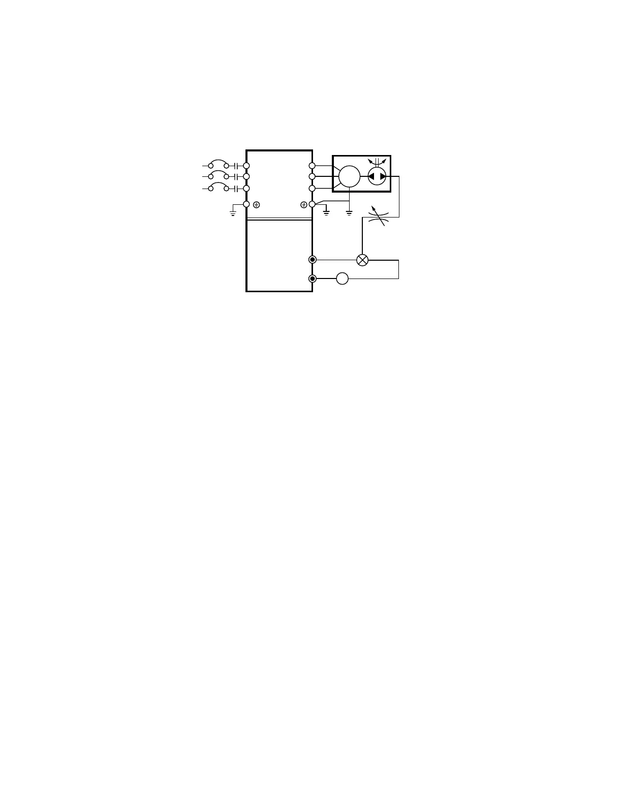
• When PID control is used in a constant pressure pump feedback application:
Set the application’s constant pressure value (bar) to be the set point of PID control. The pressure sensor will send the actual
value as PID feedback value. After comparing the PID set point and PID feedback, there will be an error. Thus, the PID
controller needs to calculate the output by using proportional gain (P), integral time (I) and differential time (D) to control the
pump. It controls the drive to have different pump speed and achieves constant pressure control by using a 4-20mA signal
corresponding to 0-10 bar as feedback to the drive.
1. Pr.00-04 is set to 10 (Display PID analog feedback signal value (b) (%))
2. 2. Pr.01-12 Acceleration Time will be set as required
3. 3. Pr.01-13 Deceleration Time will be set as required
4. 4. Pr.00-15=0 to operate from the digital keypad
5. 5. Pr.00-14=0, the set point is controlled by the digital keypad
6. 6. Pr.08-00=1 (Negative PID feedback from analog input)
7. 7. ACI analog input Pr. 03-01 set to 5, PID feedback signal.
8. 8. Pr.08-01-08-03 will be set as required
8.1 If there is no vibration in the system, increase Pr.08-01(Proportional Gain (P))
9. 8.2 If there is no vibration in the system, reduce Pr.08-02(Integral Time (I)
• Refer to Pr.08-00 to 08-20 for PID parameters settings.
• It is used to eliminate the system error. It is usually used to decrease the error and get the faster response speed. But if setting
too large value in Pr.08-01, it may cause the system oscillation and instability.
• If the other two gains (I and D) are set to zero, proportional control is the only one effective.
• The integral controller is used to eliminate the error during stable system. The integral control doesn’t stop working until error
is 0. The integral is acted by the integral time. The smaller integral time is set, the stronger integral action will be. It is helpful to
reduce overshoot and oscillation to make a stable system. At this moment, the decreasing error will be slow. The integral
control is often used with other two controls to become PI controller or PID controller.
• This parameter is used to set the integral time of I controller. When the integral time is long, it will have small gain of I
controller, the slower response and bad external control. When the integral time is short, it will have large gain of I controller,
the faster response and rapid external control.
• When the integral time is too small, it may cause system oscillation.
a
08 - 01 Proportional Gain (P)
Factory Setting: 1.0
Settings 0.0~500
a
08 - 02 Integral Time (I)
Factory Setting: 1.00
Settings 0.00~100.00 seconds
0.00: Disable
M33690
R(L1) R(L1)
S(L2)
T(L3)
S(L2)
T(L3)
U(T1)
V(T2)
W(T3)
DC
THROTTLE
WATER PUMP
NO FUSE BREAKER
(NFB)
PRESSURE
SENSOR
–
+
ACI/AVI
(4-20mA / 0-10V)
ACM
ANALOG SIGNAL COMMON
FEEDBACK
4 20mA
CORRESPONDS
0 10BAR
IM
3~
 Loading...


