23 63-4528-04
CHAPTER 5: MAIN CIRCUIT TERMINAL
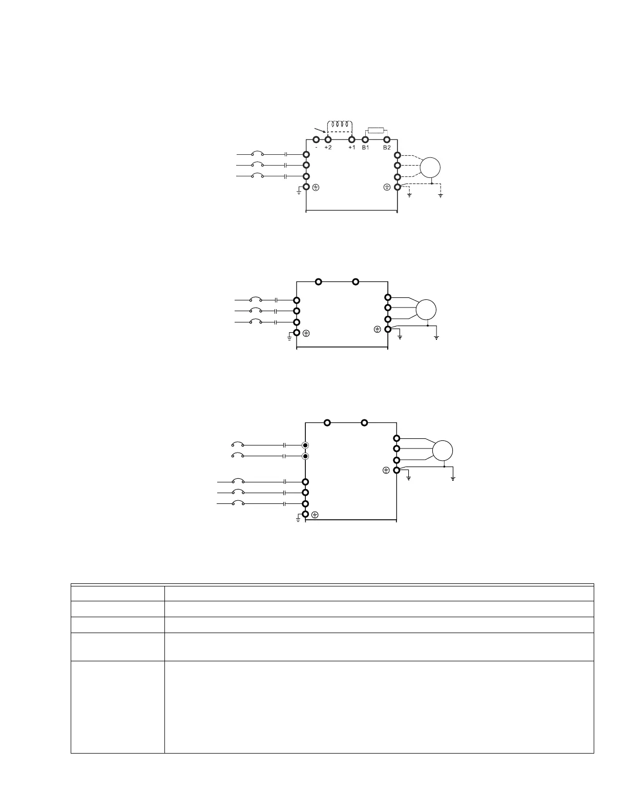
Fig. 1. Main Circuit Terminal of Frame A~C.
Fig. 2. Main Circuit Terminal of Frame D.
Fig. 3. Main Circuit Terminal of Frame E.
Table 1. Control Connections
Terminals Descriptions
R/L1, S/L2, T/L3 AC line input terminals 3-phase
U/T1, V/T2, W/T3 VFD output terminals for connecting 3-phase induction motor
+1, +2
Applicable to frame A~C
Connections for DC reactor to improve the power factor. One needs to remove the jumper for installation.
+1/DC+, -/DC-
Applicable to frame D~E
Connections for brake unit
(for 230V models: 22kW, built-in brake unit)
(for 460V models: 30kW, built-in brake unit)
Common DC Bus
When connecting DC+ and DC-, please follow the required wired gauge in Honeywell VFD CORE user
manual.
R(L1)
S(L2)
T(L3)
R(L1)
S(L2)
T(L3)
NFB
U(T1)
V(T2)
W(T3)
MOTOR
JUMPER
DC CHOKE
(OPTIONAL)
BREAKING RESISTOR
(OPTIONAL)
IM
3~
3-PHASE POWER IS PROVIDED
FUSE/NO FUSE BREAKER
M33248
U(T1)
V(T2)
W(T3)
MOTOR
IM
3~
3-PHASE POWER IS PROVIDED
R(L1)
S(L2)
T(L3)
R(L1)
S(L2)
T(L3)
NFB
FUSE/NO FUSE BREAKER
+1/DC+
-/DC+
M33249
U(T1)
V(T2)
W(T3)
MOTOR
IM
3~
3-PHASE POWER IS PROVIDED
R(L1)
S(L2)
T(L3)
R(L1)
S(L2)
T(L3)
NFB
FUSE/NO FUSE BREAKER
+1/DC+
-/DC+
r
s
R
S
M33250