CHAPTER 12: DESCRIPTION OF PARAMETER SETTINGS
63-4528—04 208
controlled by the P action only, and sometimes, if the integral component is functioning, the whole system will be vibrating. On
such occasions, in order to make the P action’s vibration subsiding and the system stabilizing, the PD control could be utilized.
In other words, this control is good for use with loadings of no brake functions over the processes.
• PID Control: Utilize the I action to eliminate the deviation and the D action to restrain the vibration, thereafter, combine with the
P action to construct the PID control. Use of the PID method could obtain a control process with no deviations, high accuracies
and a stable system.
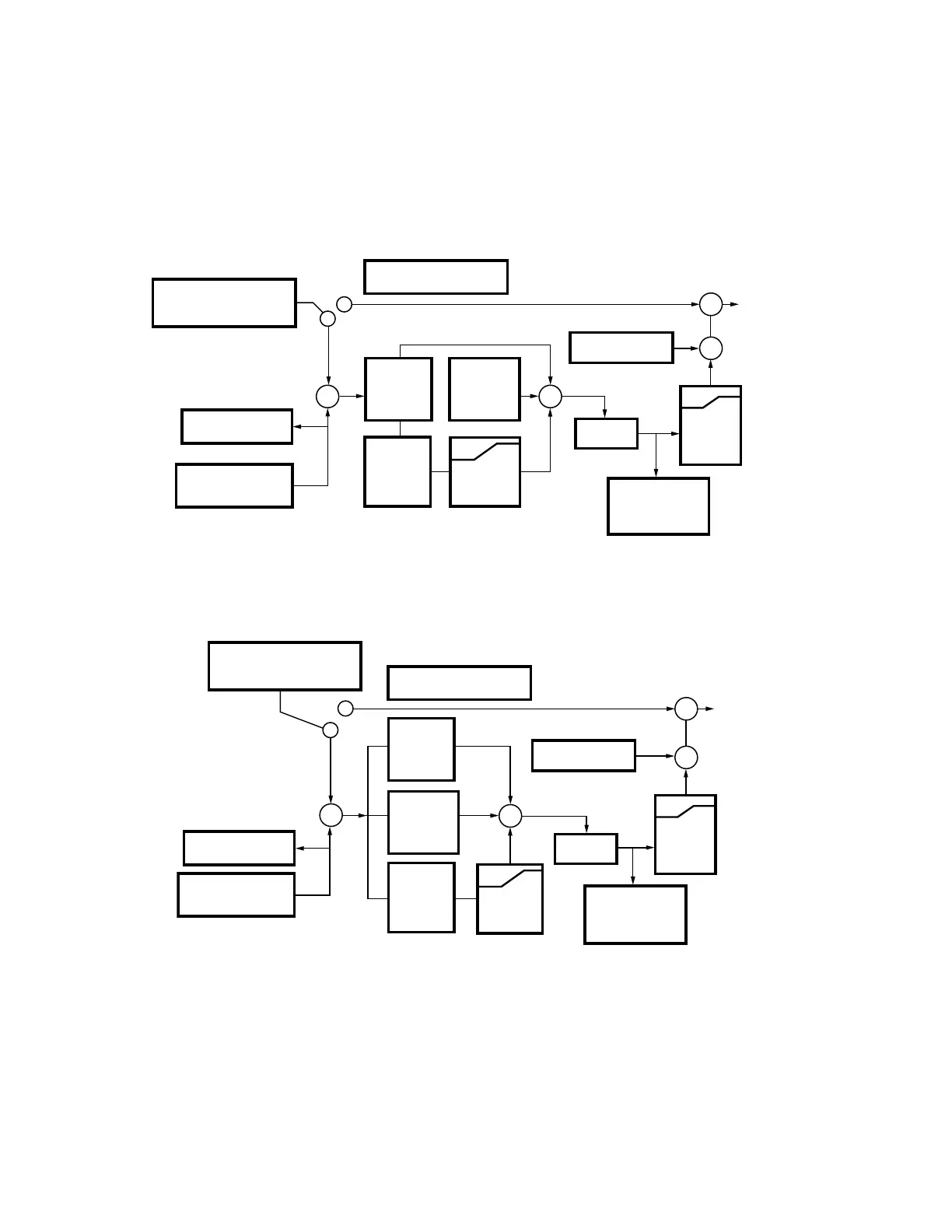
Serial Connection
Parallel connection
• This parameter is only valid when the feedback signal is ACI.
a
08 - 07 Feedback Signal Detection Time
Factory Setting: 0.0
Settings 0.0~3600.0 seconds
M33691
INPUT SELECTION OF THE
PID TARGETED VALUE
00-14:KPC-CC01/RS485
03-00 ~ 02: UP/DOWN KEY PG
DISPLAY OF THE PID
FEEDBACK 00-04 10
INPUT SELECTION OF
THE PID FEEDBACK
08-00:AVI/ACI AUI/PG
PID CANCELLED 08-00 0 OR
02-01~ 06 21 (PID OFF)
FREQUENCY
COMMAND
PID COMPENSATION
08-16
PID DELAY
TIME 08-06
08-05
PID FREQ.
OUTPUT
COMMAND
LIMIT
08-08 TREATMENT
OF THE FEEDBACK
SIGNAL FAULT IF
Hz>08-05 TIME
EXCEEDS 08-08
PROPORTION
GAIN 08-01
DIFFERENTIAL
TIME 08-03
08-02
INTEGRAL
TIME
08-04
UPPER
LIMIT FOR
INTEGRAL
+
++
P
D
I
2
1
+
+
+
M33692
INPUT SELECTION OF THE
PID TARGETED VALUE
00–14:KPC-CC01/RS485
03–00 ~ 02: UP/DOWN KEY PG
DISPLAY OF THE PID
FEEDBACK 00–04 10
INPUT SELECTION OF
THE PID FEEDBACK
08–00:AVI/ACI AUI/PG
PID CANCELLED 08–00 0 OR
02–01~ 06 21 (PID OFF)
FREQUENCY
COMMAND
PID COMPENSATION
08–16
PID DELAY
TIME 08–06
08–05
PID FREQ.
OUTPUT
COMMAND
LIMIT
08-08 TREATMENT
OF THE FEEDBACK
SIGNAL FAULT IF
Hz > 08–05 TIME
EXCEEDS 08-07
+
+
PROPORTION
GAIN 08–01
P
DIFFERENTIAL
TIME 08–03
D
08–02
INTEGRAL
TIME
I
2
1
08–04
UPPER
LIMIT FOR
INTEGRAL
 Loading...


