CHAPTER 12: DESCRIPTION OF PARAMETER SETTINGS
63-4528—04 216
ASCII mode
RTU mode
10H: write multiple registers (write multiple data to registers)
Example: Set the multi-step speed,
Pr.04-00=50.00 (1388H), Pr.04-01=40.00 (0FA0H). VFD address is 01H.
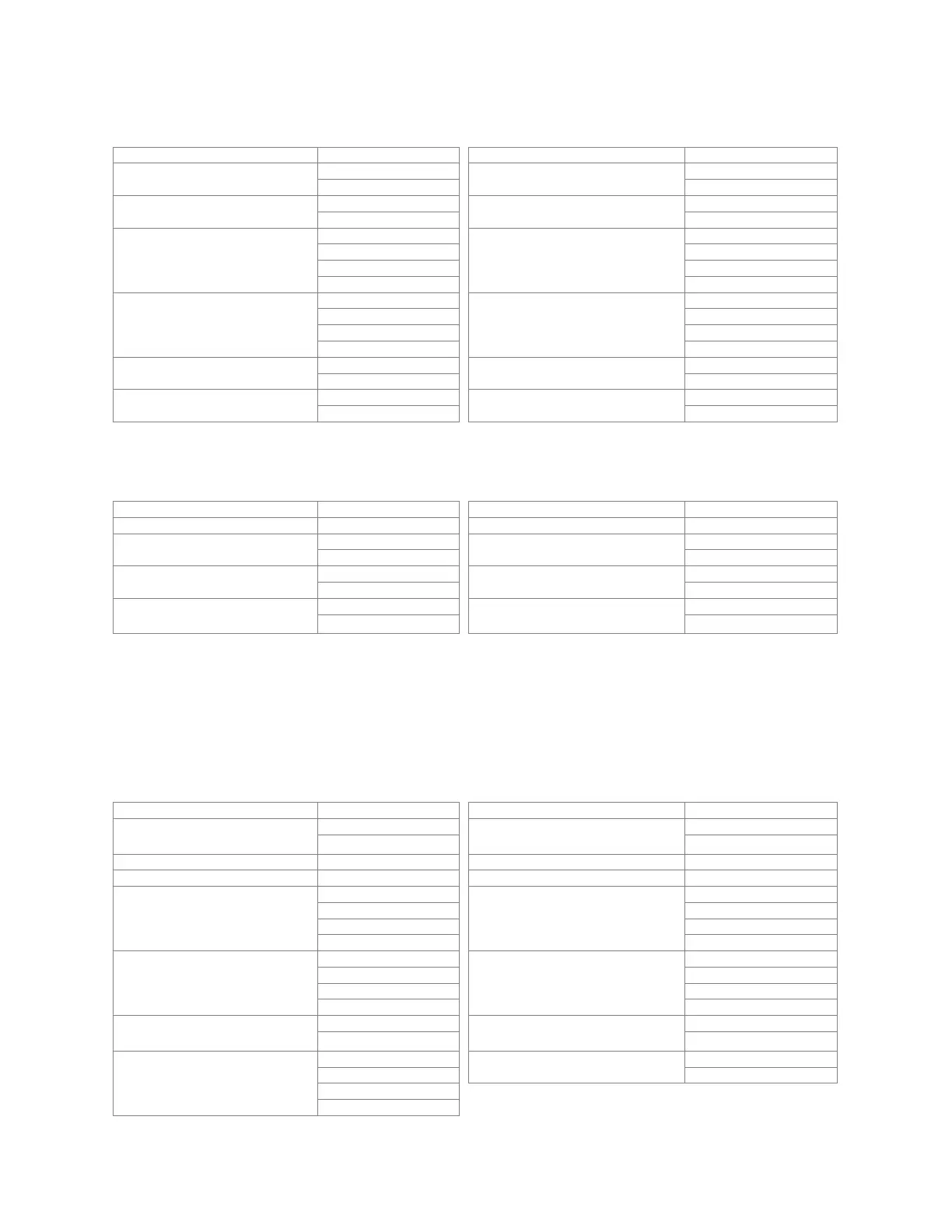
ASCII Mode
Command Message: Response Message
STX ‘:’ STX ‘:’
Address
‘0’
Address
‘0’
‘1’ ‘1’
Function
‘0’
Function
‘0’
‘6’ ‘6’
Data address
‘0’
Data address
‘0’
‘1’ ‘1’
‘0’ ‘0’
‘0’ ‘0’
Data content
‘1’
Data content
‘1’
‘7’ ‘7’
‘7’ ‘7’
‘0’ ‘0’
LRC Check
‘7’
LRC Check
‘7’
‘1’ ‘1’
END
CR
END
CR
LF LF
Command Message: Response Message
Address 01H Address 01H
Function 06H Function 06H
Data address
01H
Data address
01H
00H 00H
Data content
17H
Data content
17H
70H 70H
CRC CHK Low
CRC CHK High
86H CRC CHK Low
CRC CHK High
86H
22H 22H
Command Message: Response Message
STX ‘:’ STX ‘:’
ADR 1
ADR 0
‘0’ ADR 1
ADR 0
‘0’
‘1’ ‘1’
CMD 1 ‘1’ CMD 1 ‘1’
CMD 0 ‘0’ CMD 0 ‘0’
Starting data address
‘0’
Starting data address
‘0’
‘5’ ‘5’
‘0’ ‘0’
‘0’ ‘0’
Number of data
(count by word)
‘0’
Number of data
(count by word)
‘0’
‘0’ ‘0’
‘0’ ‘0’
‘2’ ‘2’
Number of data
(count by byte)
‘0’
LRC Check
‘E’
‘4’ ‘8’
The first data content
‘1’
END
CR
‘3’ LF
‘8’
‘8’
 Loading...


