CHAPTER 5: MAIN CIRCUIT TERMINAL
27 63-4528-04
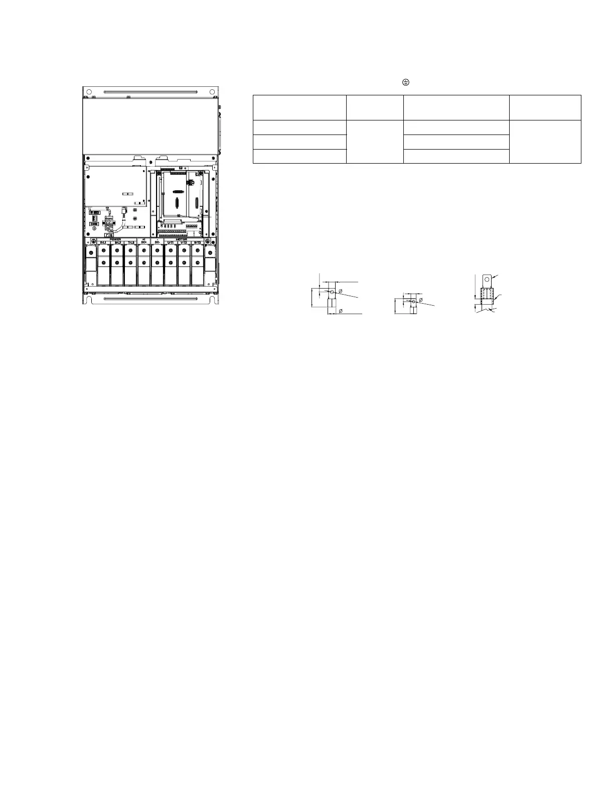
Main Circuit Terminals:
R/L1, S/L2, T/L3, U/T1, V/T2, W/T3, +1/DC+, -/DC-
1. UL installations must use 600V, 75
o
C or 90
o
C wire. Use copper wire
only.
2. Figure 1: The usage of ring terminals should comply with the specifica-
tions shown in the figure.
3. Figure 2 grounding wire specifications: 300MCM*2
[152mm2*2]TorqueM8 180Kg-cm [156 lb-in.] (17.64Nm) (±10%).
4. Figure 3 shows the specifications of insulated heat shrink tubing that
comply with UL (600C, YDPU2).
Model
Max. Wire
Gauge Min. Wire Gauge Torque (±10%)
HCRDA0750E1000T
4/0 AWG*2
(107mm2*2)
2/0 AWG*2 (67.4mm
2
*2)
M8 200kg-cm
(173 lb-in.)
HCRDA1000E1000T 3/0 AWG*2 (85mm
2
*2)
HCRDA1250E1000T 4/0 AWG*2 (107mm
2
*2)
M31491
FIGURE 1
26.5 MAX.
8.2 MIN.
31 MAX.
70 MAX
16
+0
-4
17 MAX
65 MAX
8.2 MIN.
28 MAX.
FIGURE 2
WIRE
HEAT
SHRINK
TUBE
RING LUG
FIGURE 3
13 M N
FRAME E
M33257
 Loading...


