CHAPTER 7: OPTIONAL COMPONENTS
37 63-4528—04
*
The longest operation time for 10% ED is 10 sec. (on: 10 sec.; off: 90 sec.)
**
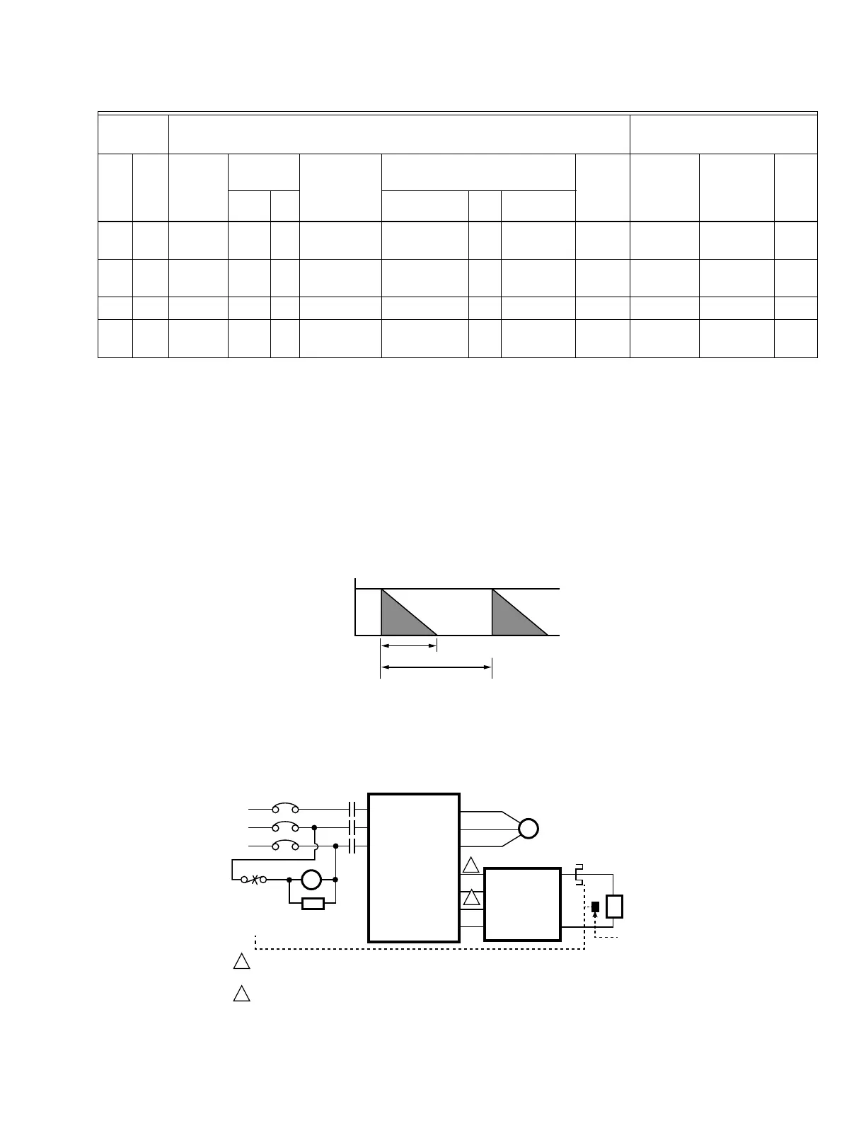
See Brake Performance Curve below for the relation between Running Time, ED(%) vs Braking Current.
***
The calculation of the maximum braking torque is based on a 4-pole motor (1800rpm)
****
For the heat dissipation, a resistor of 400W or lower should be fixed to the frame and keep the surface below 250° C (400° F).
As for a resistor of 1000W and above, the surface temperature should be kept below 600
° C. If the temperature is over the
resistor’s temperature limit, it will be necessary to add heat dissipating system or increase resistor’s power
NOTE:
1. Definition for Brake Usage ED%
Explanation: The definition of the brake usage ED (%) is for assurance of enough time for the brake unit and brake resistor
to dissipate away heat generated by braking. When the brake resistor heats up, the resistance would increase with temper-
ature, and brake torque would decrease accordingly. Recommended cycle time is one minute.
For safety concern, install an overload relay (O.L) between the brake unit and the brake resistor together with the magnetic
contactor (MC) prior to the drive to protect the drive from abnormal functions. The purpose of installing the thermal over-
load relay is to protect the brake resistor from damages due to frequent brakes, or caused by brake unit’s continuous
conductions resulted from unusual high input voltage. Under such circumstance, turn off the power to prevent damaging the
brake resistor.
60 45 25.1 4045 1
4800W 15Ω
BR1K2W015 4
2 parallel,
2 series
50 12.7 60 45.6
75 55 30.5 4045 1
6000W 13Ω
BR1K5W013 4
2 parallel,
2 series
59 12.7 60 45.6
100 75 37.2 4030 2
8000W 10.2Ω
BR1K0W5P1 4 4 series 76 9.5 80 60.8
125 90 50.8 4045 2
9600W 7.5Ω
BR1K2W015 4
2 parallel,
2 series
100 6.3 120 91.2
Table 1. 230V & 460V
Applicable
Motors
10% ED
*
Max. Braking Torque
**
HP kW
Braking
Torque
(kg-m)***
Brake Unit
Resistor
Value Spec.
for Each
VFD
Braking Resistor Series for
Each Brake Unit
Total
Braking
Current
Min.
Resistor
Value (Ω)
Max. Total
Braking
Current (A)
Peak
Power
(kW)
VFDB Unit
Part #****
Unit Connection
CYCLE TIME
BRAKE TIME
T
100%
T0
ED% T1/T0 X 100
M33296
M33297
R/L1
S/L2
T/L3
R/L1
S/L2
T/L3
NFB
MC
O. L.
SA
MC
U/T1
V/T2
W/T3
VFD
SERIES
DCM
E.F.
-
(N)
+ (P)
RC
RA
-
(N)
+ (P)
B1
B2
IM
O. L.
BR
MOTOR
SURGE
ABSORBER
THERMAL
OVERLOAD
RELAY OR
TEMPERATURE
SWITCH
VFDB
BRAKING
THERMAL
OVERLOAD
RELAY
BRAKING
RESISTOR
TEMPERATURE
SWITCH
1
2
WHEN USING THE VFD WITH DC REACTOR, PLEASE REFER TO WIRING DIAGRAM IN THE VFD
USER MANUAL FOR THE WIRING OF TERMINAL
+(P) OF BRAKING UNIT.
DO NOT WIRE TERMINAL
-
(N) TO THE NEUTRAL POINT OF POWER SYSTEM.
2
1
 Loading...


