CHAPTER 7: OPTIONAL COMPONENTS
63-4528—04 38
2. If damage to the drive or other equipment is due to the fact that the brake resistors and brake modules in use are not pro-
vided by Honeywell, the warranty will be void.
3. Consider the safety of the environment when installing the brake resistors. If the minimum resistance value is to be utilized,
consult Honeywell Technical Support for the calculation of Watt figures.
4. When using more than 2 brake units, equivalent resistor value of parallel brake unit can’t be less than the value in the col-
umn “Minimum Equivalent Resistor Value for Each VFD” (the right-most column in the table). Read the wiring information in
the user manual of the brake unit thoroughly prior to operation
5. This chart is for normal usage; if the VFD will be applied for frequent braking, it is recommended to increase the watts by
2~3 times.
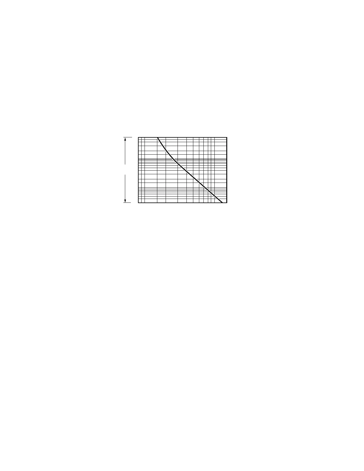
6. Thermal Relay:
Thermal relay selection is based on its overload capability. A standard braking capacity for VFD CORE is 10%ED (Tripping
time=10s). The figure below is an example of 460V, 110kw VFD. It requires the thermal relay to take 260% overload capac-
ity in 10s (Host starting) and the braking current is 126A. In this case, user should select a rated 50A thermal relay. The
property of each thermal relay may vary among different manufacturer, please read carefully specification provided by the
manufacturer.
60
40
30
20
10
8
3
2
4
6
1
0.8
0.6
0.4
0.3
0.8 1 1.5 2 3 4 5 6 8
10 15
79
XLN (A)
M33298
MULTIPLE OF CURRENT
TRIPPING
SECONDS
 Loading...


