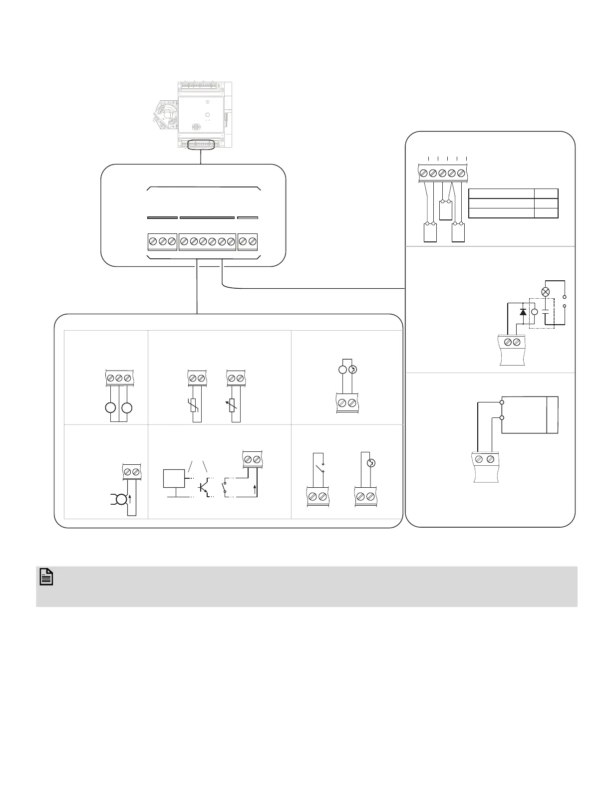
Fig. 18 Universal IO Wiring Examples
19
20
21
22
23
24
25
26
27
28
29
IO1
C
IO2
IO3
C
IO4
IO5
C
IO6
C
IO7
UIO1 - UIO7 Universal Input / Output (UIO)
UO1 - UO7 Output Connection Example
UI1 - UI7 Input Connection Example
Ensure
correct
polarity
+
-
0 to 10 VDC
V
Voltage Input
Thermistor / Resistive Input
Dry contacts / Digital Input
Current Input
100 to
100 k
:
e.g.
20 kNTC
PT1000
dry contact
contact
open
collector
Ensure correct
polarity
logic
circuit
DIGITAL
0 V
IO
C
+
-
V
V
IO
IO
C
IO
C
IO
C
S
External
Power
Supply
Ensure
co
rrect
polarity
SSS
S
0V IN
IN 0V
0V IN
Output Type Load
0 to 10 VDC, 10 mA max. 1 k:
4 to 20 mA 550:
IO
C
IO
IO
C
Externally Powered
minimum
wetting
current
3.5 mA
IO
C
Voltage Output to Power External Relay
+
-
Ensure correct
polarity
The rating of the diode
must be 11 V and 22 mA
maximum.
IO
C
0 to 10 VDC
DC LOAD
Ensure correct
polarity
Analog Output (UIO)
+
-
IO
C
Analog Output (UIO) provides a variable
voltage between 0 to10 VDC and the
output can source up to 20 mA.
Pulse Meter (Type 1: Pulse
with Power 5-30 V)
Pulse Meter (Type 2: Pulse
without Power)
IO
C
V
+
_
IO
C
IO
C
LOAD
SUPPLY
RELAY
 Loading...