SPYDER MODEL 7 VAV CONTROLLER INSTALLATION INSTRUCTIONS
31-00475-01 24
BACNET MSTP WIRING
The MSTP variants of the Spyder Model 7 VAV controller
use the BACnet MSTP communication protocol. The
controller’s data is presented to other controllers over a
twisted-pair MSTP network, using the TIA/EIA 485
signaling standard capable of the following baud rates:
9.6, 19.2, 38.4, 57.6, and 76.8 kb/s. The Spyder Model 7
BACnet MSTP controllers are server devices on the
MSTP network. Each Spyder Model 7 BACnet controller
uses a high-quality TIA/EIA 485 transceiver and exerts
1/8 unit load on the MSTP network.
According to U.L. requirements, each RS-485 interface
may be loaded with a maximum of 32 unit loads.
Depending on the actual performance and connection
speed, connecting fewer BACnet MSTP devices per
network is recommended. It is recommended to have
less than 40 controllers on a single MSTP network.
The controller features a 2-wire non-isolated RS-485
interface (terminals 32, 33, and 34) suitable for BACnet
MSTP communication. The terminal block containing it
is gray. The cable length affects the baud rate. See
Table 18.
NOTE:
The maximum length of a BACnet MSTP network
bus segment with recommended wiring is 4,000 ft
(1200 m). Repeaters must be used when making
runs longer than 4,000 ft (1200 m). Between any
two devices, a maximum of three repeaters can be
used.
Termination Resistors
Matched terminating resistors are required at each end
of a segment bus wired across (+) and (-). Use matched
precision resistors rated ¼ W ±1 % / 80 = 130 Ω.
Ideally, the value of the terminating resistors should
match the rated characteristic impedance of the
installed cable. For example, if the installed MSTP cable
has a listed characteristic impedance of 120 Ω, install a
120 Ω resistor.
RS-485 Bias Switches
Each RS-485 port has an adjacent 3-position biasing
switch, with these settings:
• BIA - (Default, middle) Controller provides RS-485
biasing, but without a termination resistor.
• END - Both RS-485 biasing and a termination
resistor are provided by the controller.
• MID - No RS-485 biasing or termination resistor is
provided by the controller.
Often, adding RS-485 biasing can improve
communications by eliminating indeterminate idle
states.
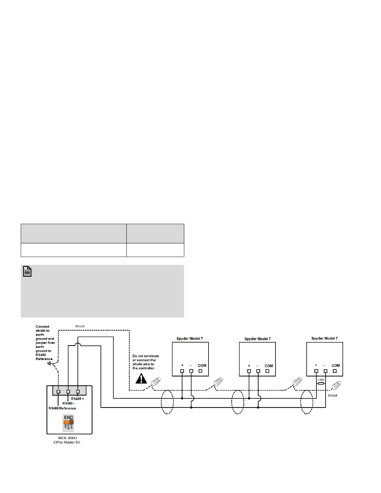
BACnet MSTP Wiring Example
Following proper MSTP cabling shield grounding
procedures is important to minimize the risk of
communication problems and equipment damage
caused by capacitive coupling. Capacitive coupling is
caused by placing MSTP cabling close to lines carrying
higher voltage. The shield should be grounded on only
one end of the MSTP segment, for example, on the earth
ground terminal on the WEB-8000 and to earth ground.
Fig. 28 BACnet MSTP Wiring Example with WEB-8000 or CIPer Model 50
Table 18 Baud Rate vs Maximum Cable Length
Baud Rate
Maximum Cable
Length (L)
9.6, 19.2, 38.4, 57.6, and 76.8 kbps
4000 ft (1200 m)
 Loading...