Particular features of the room unit HCW 80
8. Particular features of the
room unit HCW 80
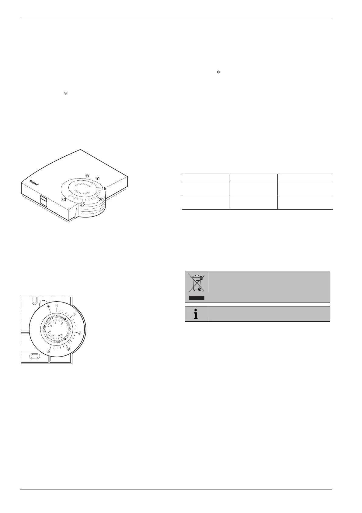
► Place the two small pins into the holes of the adjustment
dial in order to limit the adjustment range (see Fig. 16).
Orientate yourself on the basis of the inner scale:
In
Fig. 16, the pins are inserted so that the adjustment dial
can only be adjusted in the range of 19 °C to frost
protection
8.1. Operation
(lower limit) and 19 °C to 30 °C (higher limit)
around the value 19 °C.
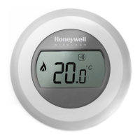
The room set point temperature can be set easily at the set
point adjuster by means of an adjustment dial. The room set
point range is from 10 °C to 30 °C including the frost
protection setting
► Turn the adjustment dial clockwise until it stops.
(5 °C).
► Check whether the adjustment dial is in the position shown
in
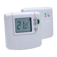
The HCW 80 simulates a mechanical thermostat by LED
indication as follows:
Fig. 15.
► If appropriate, put the adjustment back in, rotated by 180°
until it has the position shown.
The red LED at the HCW 80 will be switched ON for 4 sec if
the deviation between the set point and the room
temperature is >1 °C. If the deviation is <1 °C the red LED is
flashing for 4 sec. Respectively the relay module HC60NG
will be switched ON or OFF.
► Turn the adjustment dial to position 19.
► Place the housing cover in position above and snap it
down (see Fig. 14, Page 8).
8.3. Fixed control parameters
T
he following parameters will be used for the control:
Parameter Factory setting Remark
1 minute
Minimum ON
time
Minimum power up
time within the cycle
Cycle rate 6 cycles per hour
Pulse width
modulation per hour
9. Changing batteries
Fig. 15: Room unit HCW 80 (settings on the scale in °C)
Change the batteries if the red LED of the room unit
HCW 80 flashes and the device is not in test mode.
► Select the desired room temperature set point at the
adjustment dial (see Fig. 15).
► Remove the housing cover of the HCW 80 (see Fig. 11,
Page
8).
► Remove the batteries.
8.2. Limiting the adjustment range
You can limit the adjustment range that can be used at the
adjustment dial.
Dispose of the batteries according to the local
► Remove the housing cover (see Fig. 11, Page 8).
statutory requirements and not with the domestic
refuse.
Fig. 16: Limiting the adjustment range
Always replace both batteries together. Only use
1.5 V batteries of the type LR06, AA.
► Insert the batteries with the correct polarity into the battery
compartment (see
Fig. 13, Page 8).
► Place the housing cover on at the top and latch it in
downwards (see Fig. 14, Page 8).
10
 Loading...