Installation
max. 2.5 mm
2
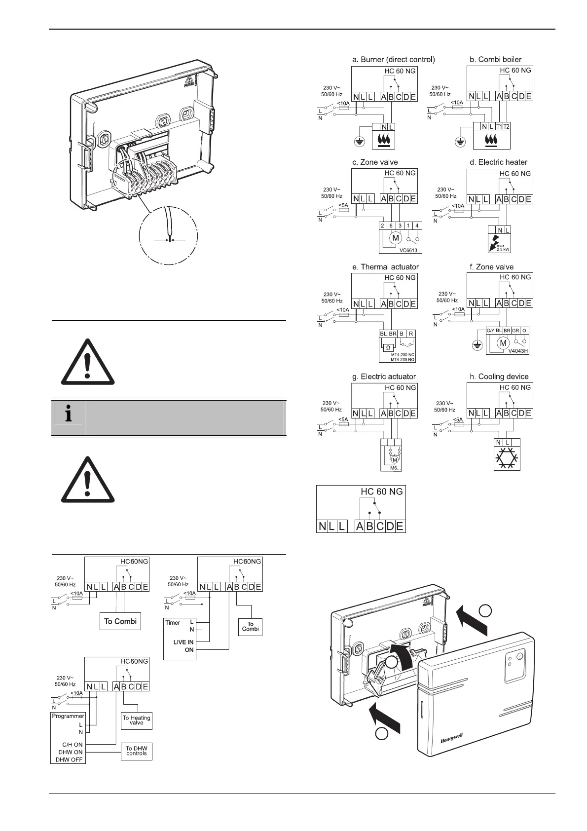
Fig. 6: Wiring the terminal
3.1.1. Connections for HC60NG
(R6660D1009)
CAUTION Incorrect wiring!
► Install in accordance with local wiring
regulations.
► Observe ambient temperature and
current limits (see HC60NG wiring
label).
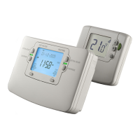
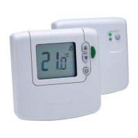
The green LED on the receiver indicates demand
from the thermostat NOT that the heating will be
on, this depends on the programmer settings.
CAUTION Incorrect wiring!
Honeywell accepts no liability for any
loss or damage arising from any errors
or omissions that may be inadvertently
contained within this sketch. This is a
proposal sketch only, not a certified
wiring diagram.
Output rating
24–230 V AC
A-B max. 6.5 A (3 A, cos φ = 0.6)
► This diagram must be read in
conjunction with any boiler or cylinder
manufacturers instructions.
A-C max. 5.0 A (3 A, cos φ = 0.6)
Fig. 8: Wiring diagram for HC60NG
1
2
2
Fig. 9: Closing the terminal and housing cover
Fig. 7: Wiring diagram for HC60NG
7
 Loading...