To get the operator up and running, check the items outlined below-
1. SLIDE OPERATOR QUICK START INSTRUCTIONS FOR SERIES 2000 LINEAR DRIVES & SERIES 2000B, 2001 & 2003 BELT DRIVES
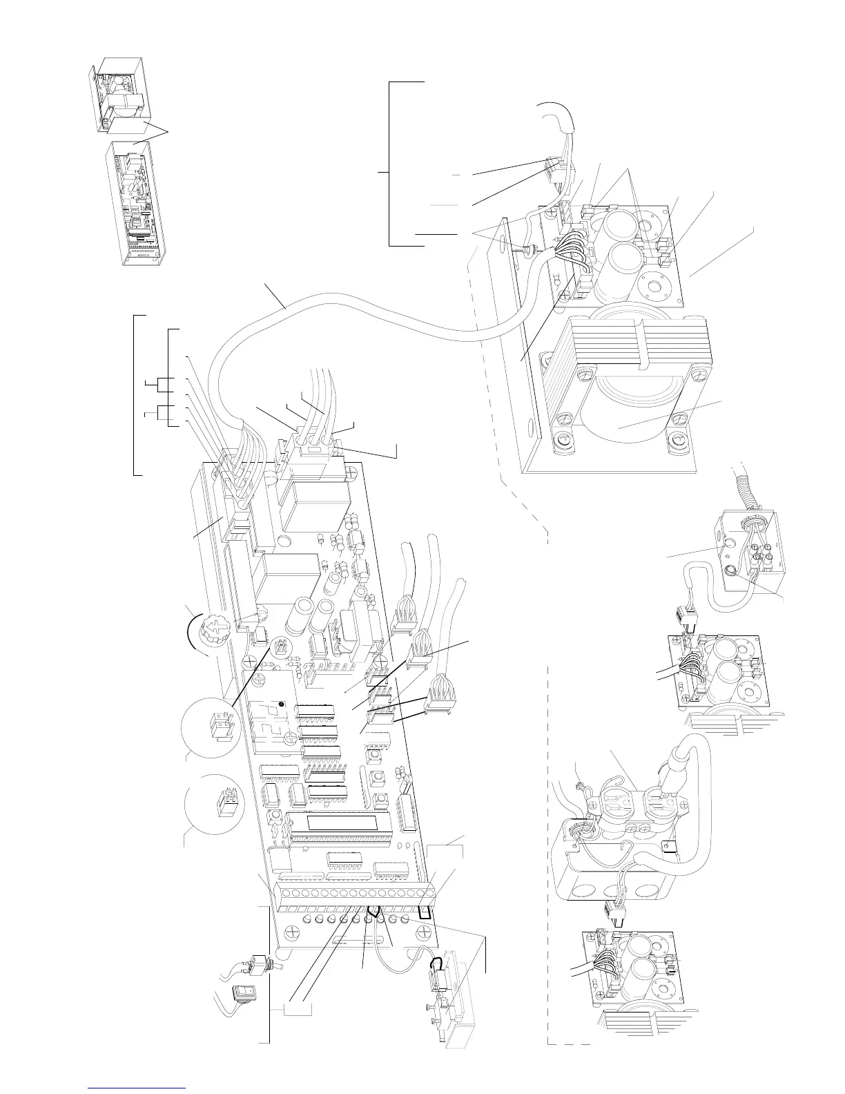
The encoder must be plugged into
CN1 on the control.
(The Linear Drive must be plugged
into CN 11)
TO
LINEAR DRIVE
TO
AUTOLOCK
Temporarily turn the reversing sensitivity
completely counter-clockwise.
CN 7
FIELD WIRING
OPTION 2
F
2
F
3
F
1
Field wiring options
If the day / night mode is
NOT
to be used - there
MUST
be a
jumper between 15 & 16.
See Sections 5 thru 10 for actuating
features and lock set-up.
With wiring option 1, 2 or 3
The main ground wire must secured using
the green grounding screw.
F
2
F
3
F
1
3rd Step
IMPORTANT
05/08
2.0468d
The close monitor switch(Belt Drives)
must be connected to #10 & #11 of
CN2. The switch must trip when the
door is fully closed.
2nd Step
15
16
FIELD WIRING
OPTION 3
Grounding
screw
Grounding
screw
4th Step
C2150 Control with version 10 software - S/N 08030006-________
Linear Drive
(ENC)
Do
NOT
wire any motion detectors or any other accessories at this time.
Factory pre-wired beams (pins 5,6 & 7) may be left in place.
Verify jumpers JB1A & JB1B
10th Step
2001
switch
11
10
2003
switch
9
8
V-XXXX
D
1
CN 2
A toggle switch or jumper must
be present between pins 8 & 9.
Switches are sent loose and field
mounted. Break-outs are wired in
series with the toggle switch .
1st Step
CN 11
CN 4
C
N
5
CN 1
Belt Drive
(ENC)
9th Step
The motor must be
plugged into connector
CN8
Neutral WHT U.S. - BLU Int.
H210.1
F
2
POWER SUPPLY
C3925 for 120VAC-2001 (shown)
C3955 for 120VAC-2003
C3926 for 240VAC-2001
C3956 for 240 VAC-2003
TO
ENCODER
CN 2
Master
fuse
F 1
+27 to +35VDC
& processor
NOTE:
Component arrangement
may vary.
Motor
+100 to +120
VDC
All fuses are
5x20 mm Type "T"
Rated 3.15 amp
F 2
F
3
F 3
CN 1
FIELD WIRING
OPTION 1
AC POWER IN
Line (Hot side)
BLK U.S. - BRN Int.
F
1
2
3
1
A 5 conductor cable attaches
CN7 to the power supply.
7th Step
5th Step
GRN / YEL
motor ground
BLK
CN 8
TO
MOTOR
RED
Incoming voltages
from power supply
1 2 3 4 5GND
8th Step
+100 to +120
VDC from F2
+27 to + 35
VDC from F3
NOTE:
On 2001 & 2003
Metal shields are
REQUIRED
by UL
for protection against
high voltage areas
Do not remove.
Ground GRN U.S. - GRN / YEL Int.
(Connect to grounding screw)
Check that the incoming power
is wired as shown.
6th Step
Shields and chassis
are not shown in this
manual for clarity