Model 141A
Sectim
111
Paragraphs 3-1 to 3-16
SECTION
111
0
PER
AT1
0
N
3-8.
REAR PANELCOMPONENTS.
i
I
I
3-1.
INTRODUCTION
3-2. The Model 141Ais avariablepersistence, stor-
age Oscilloscope which employs plug-in
type
vertical
and horizontal amplifiers. The controls which affect
the operation of the power supplies and cathode ray
tube
are
located on the Model 141A; all other controls
are
locatedon
the plug-inamplifiers.
The Model 141A
includes the high and low-voltage power supplies,
a
calibrator circuit with
1
and 10-volt pk-pk outputs on
the front panel, the CRT, andapulsecircuit for vari-
able persistence and storage operation.
3-3.
FRONT PANEL COMPONENTS.
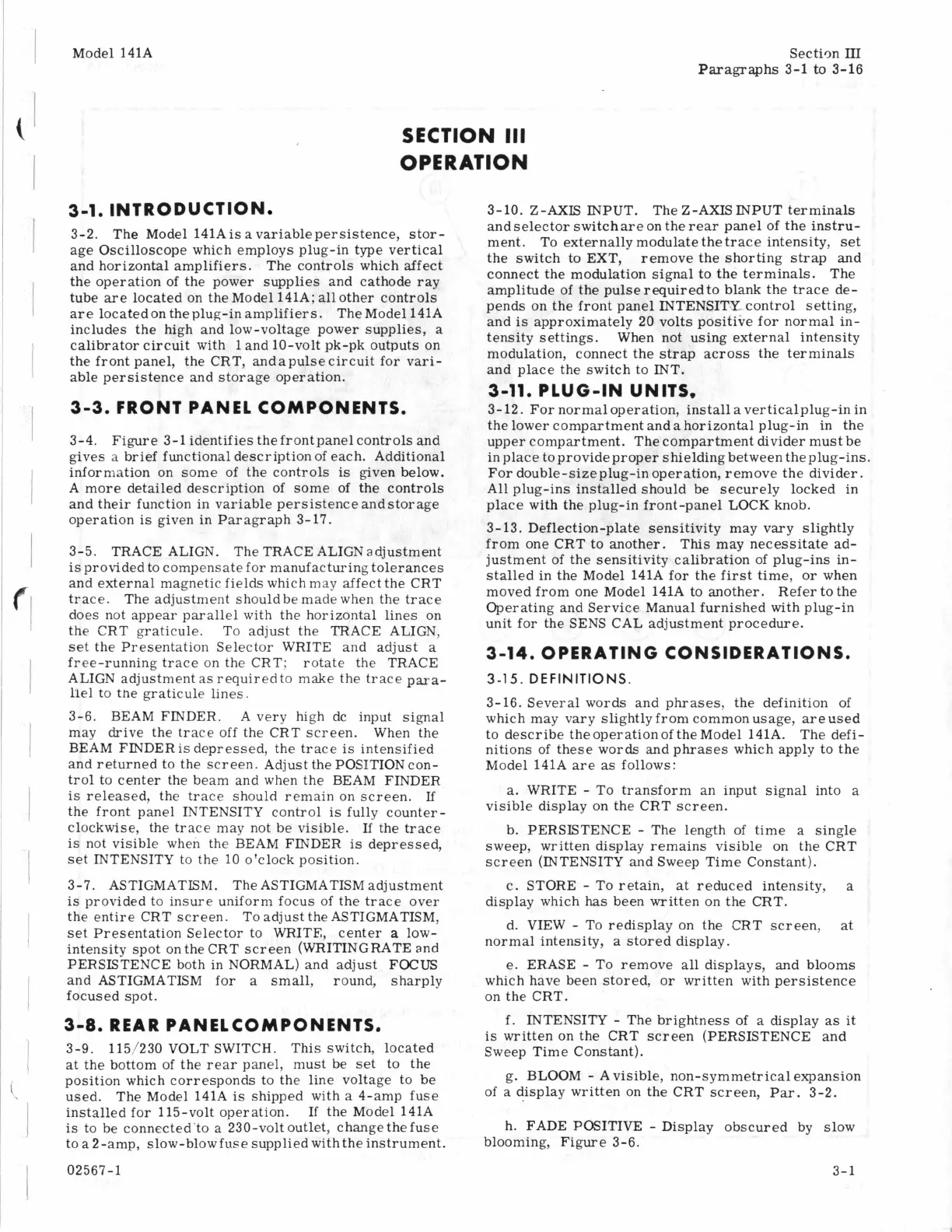
3-4.
Figure
3-1 identifies thefrontpanelcontrols and
gives
a
brief functional description of each. Additional
information on some of the controls
is
given below.
A more detailed description of some of the controls
and their function in variable persistence andstorage
operation
is
given in Paragraph 3-17.
3-5. TRACE ALIGN. The TRACE ALIGNadjustment
is
provided to compensate for manufacturing tolerances
and external magnetic fields which may affect the CRT
trace. The adjustment shouldbe made when the trace
does not appear parallel with the horizontal lines on
the CRT graticule. To adjust the TRACE ALIGN,
set the Presentation Selector WRITE and adjust
a
free-running trace on the CRT; rotate the TRACE
ALIGN adjustment
as
requiredto make the trace
para-
llel
to
the graticule lines.
3-6. BEAM FINDER.
A
very high dc input signal
may drive the trace off the CRT screen. When the
BEAM FINDERis depressed, the trace
is
intensified
and returned to the screen. Adjust the POSITIONcon-
trol to center the beam and when the BEAM FINDER
is
released, the trace should remain on screen.
If
the front panel INTENSITY control is fully counter-
clockwise, the trace may not be visible. If the trace
is
not visible when the BEAM FINDER
is
depressed,
set INTENSITY to the 10 o'clock position.
3-7. ASTIGMATLSM. The ASTIGMATISM adjustment
is
provided to insure uniform focus of the trace over
the entire CRT screen. To adjust the ASTIGMATISM,
set Presentation Selector to WRITE, center
a
low-
intensity spot on the CRT screen (WRITINGRATE and
PERSISTENCE both in NORMAL) and adjust FOCUS
and ASTIGMATISM for
a
small, round, sharply
focused spot.
3-9. 115/230 VOLT SWITCH. This switch, located
at the bottom of the
rear
panel, must be set to the
position which corresponds to the line voltage to be
used. The Model 141A
is
shipped with
a
4-amp fuse
installed for 115-volt operation. If the Model 141A
is
to be connected'to
a
230-volt outlet, changethe fuse
to
a
2-amp, slow-blow fuse supplied with the instrument.
02567-1
3-10. Z-AXIS INPUT.
andselector switchare on the
rear
panel
of
the instru-
ment. To externally modulate the trace intensity,
set
the switch to EXT, remove the shorting strap and
connect the modulation signal to the terminals. The
amplitude of the pulse required to blank the trace de-
pends on the front panel INTENSITY- control setting,
and
is
approximately 20 volts positive for normal in-
tensity settings. When not using external intensity
modulation, connect the strap across the terminals
and place the switch to INT.
3-11.
PLUG-IN UNITS,
3-12. For normaloperation, install averticalplug-in in
the lower compartment anda horizontal plug-in in the
upper compartment. The compartment divider must be
in place to provideproper shielding between theplug-ins.
For double-sizeplug-in operation, remove the divider.
All plug-ins installed should be securely locked in
place with the plug-in front-panel LOCK knob.
3-13. Deflection-plate sensitivity may vary slightly
from one CRT to another. This may necessitate ad-
justment of the sensitivity calibration of plug-ins in-
stalled in the Model 141A for the first time, or when
moved from one Model 141A to another. Refer to the
Operating and Service Manual furnished with plug-in
unit for the SENS CAL adjustment procedure.
The Z-AXIS INPUT terminals
3-1
4.0
PER AT
IN
G
CONS
ID
ERA1 IONS.
3-15.
DEFINITIONS.
3-16. Several words and phrases, the definition of
which may vary slightlyfrom commonusage, areused
to describe the operationof theModel 141A. The defi-
nitions of these words and phrases which apply to the
Model 141A
are
as
follows:
a.
WRITE
-
To transform an input signal into
a
visible display on the CRT screen.
b. PERSISTENCE
-
The length of time
a
single
sweep, written display remains visible on the CRT
screen (INTENSITY and Sweep Time Constant).
c. STORE
-
To retain, at reduced intensity,
a
display which
has
been written on the CRT.
d. VIEW
-
To redisplay on the CRT screen, at
normal intensity,
a
stored display.
e.
ERASE
-
To remove
all
displays, and blooms
which have been stored, or written with persistence
on the CRT.
f.
INTENSITY
-
The brightness of
a
display
as
it
is
written on the CRT screen (PERSISTENCE and
Sweep Time Constant).
of
a
display written on the CRT screen,
Par.
3-2.
g. BLOOM
-
A visible, non-symmetrical expansion
h. FADE POSITIVE
-
Display obscured by slow
blooming, Figure 3-6.
3-
1