Model 141A
Section
IV
Paragraphs 4-32
to
4-41
r
h
PULSE PULSE
G
E NE R ATOR AMPLIFIER
-
TO CRT
07034706
Q707/0700
MULTIVIERATOR
Q701/0702
.
1411-8-2
\
,
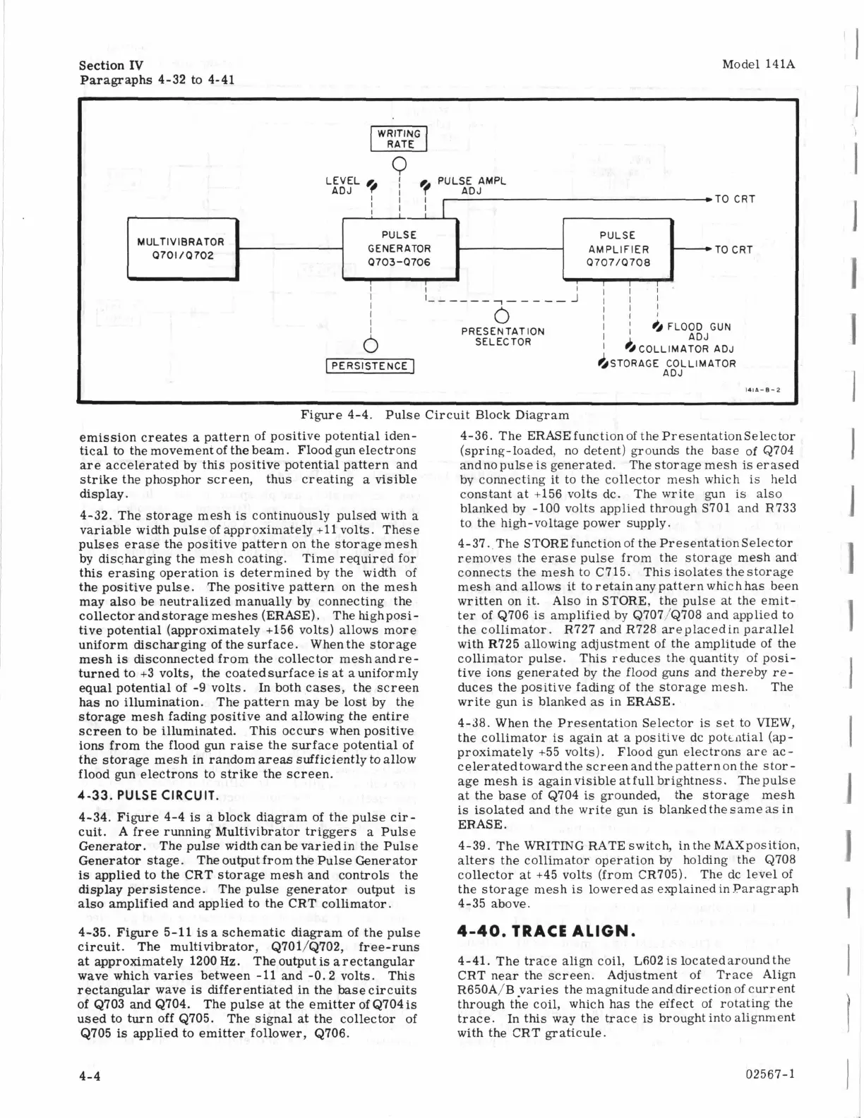
Figure 4-4. Pulse Circuit Block Diagram
emission creates
a
pattern of positive potential iden-
tical to the movement of the beam. Flood gun electrons
are
accelerated by this positive potential pattern and
strike the phosphor screen, thus creating
a
visible
display.
4-32. The storage mesh
is
continuously pulsed with
a
variable width pulse of approximately
+11
volts. These
pulses erase the positive pattern on the storage mesh
by discharging the mesh coating. Time required for
this erasing operation
is
determined by the width of
the positive pulse. The positive pattern on the mesh
may also be neutralized manually by connecting the
collector andstorage meshes (ERASE). The highposi-
tive potential (approximately +156 volts) allows more
uniform discharging of the surface. Whenthe storage
mesh
is
disconnected from the collector meshandre-
turned to +3 volts, the coatedsurface
is
at auniformly
equal potential of -9 volts. In both cases, the screen
has no illumination. The pattern may be lost by the
storage mesh fading positive and allowing the entire
screen to be illuminated. This occurs when positive
ions from the flood gun raise the surface potential of
the storage mesh in random areas sufficiently toallow
flood gun electrons to strike the screen.
4-33.
PULSE CIRCUIT.
4-34. Figure 4-4
is
a
block diagram of the pulse cir-
cuit.
A
free running Multivibrator triggers a Pulse
Generator. The pulse width can be variedin the Pulse
Generator stage. The output from the Pulse Generator
is
applied to the CRT storage mesh and controls the
display persistence. The pulse generator output
is
also amplified and applied to the CRT collimator.
4-35. Figure 5-11
isa
schematic diagram of the pulse
circuit. The multivibrator, Q701/Q702, free-runs
at
approximately 1200
Hz.
The output
is
arectangular
wave which varies between
-11
and -0.2 volts. This
rectangular wave
is
differentiated in the base circuits
of Q703 and Q704. The pulse at the emitter of Q704
is
used to turn off Q705.
The signal
at
the collector of
Q705
is
applied to emitter follower, Q706.
4-36. The ERASEfunction
of
the PresentationSelector
(spring-loaded, no detent) grounds the base
of
Q704
andnopulse
is
generated. The storage mesh
is
erased
by connecting it to the collector mesh which
is
held
constant at +156 volts dc. The write gun is also
blanked by -100 volts applied through S701 and R733
to the high-voltage power supply.
4-37. The STORE function of the PresentationSelector
removes the erase pulse from the storage mesh and
connects the mesh to C715. This isolates the storage
mesh and allows it to retain any pattern which has been
written on it.
Also in STORE, the pulse at the emit-
ter of Q706
is
amplified by Q707/Q708 and applied to
the collimator. R727 and R728 areplacedin parallel
with R725 allowing adjustment of the amplitude of the
collimator pulse. This reduces the quantity of posi-
tive ions generated by the flood guns and thereby
re-
duces the positive fading of the storage mesh. The
write gun
is
blanked
as
in ERASE.
4-38. When the Presentation Selector
is
set to
VIEW,
the collimator
is
again at a positive dc pottntial (ap-
proximately +55 volts). Flood gun electrons are ac-
celeratedtoward the screenandthe patternon the stor
-
age mesh
is
againvisible atfull brightness. Thepulse
at the base of Q704
is
grounded, the storage mesh
is
isolated and the write gun
is
blankedthe same
as
in
ERASE.
4-39. The WRITING RATE switch, in the MAXposition,
alters the collimator operation by holding the Q708
collector at
+45
volts (from CR705). The dc level of
the storage mesh
is
loweredas explainedinParagraph
4-35 above.
4-40.
TRACE
ALIGN.
4-41. The trace align coil, L602is locatedaroundthe
CRT near the screen. Adjustment of Trace Align
R650A/B varies the magnitude and direction of current
through the coil, which has the eifect of rotating the
trace. In this way the trace
is
brought into alignment
with the CRT graticule.
I
I
I
1
1
1
I
1
I
1
1
I
I
I
4-4
02567-1