Model
141A
SECTION
IV
PRINCIPLES
OF
OPERATION
Section
IV
Paragraphs 4-
1
to 4- 10
4-1.
OVERALL FUNCTIONAL
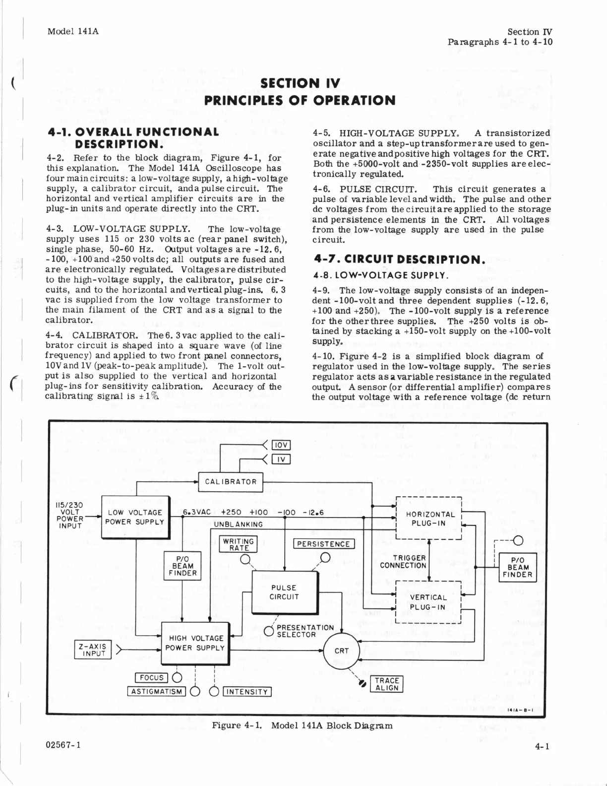
4-2. Refer to the block diagram, Figure 4-1, for
this explanation. The Model
141A
Oscilloscope has
four main circuits:
a
low-voltage supply, a high-voltage
supply, a calibrator circuit, anda pulse circuit. The
horizontal and vertical amplifier circuits are in the
plug-in units and operate directly into the CRT.
DESCRIPTION.
4-3. LOW-VOLTAGE SUPPLY. The low-voltage
supply uses 115 or 230 voltsac (rear panel switch),
single phase, 50-60
Hz.
Output voltages
are
-12.6,
-
100, +lo0 and +250 volts dc; all outputs are fused and
are electronically regulated. Voltagesare distributed
to the high-voltage supply, the calibrator, pulse cir-
cuits, and to the horizontal andverticalplug-ins. 6. 3
vac
is
supplied from the low voltage transformer to
the main filament of
the
CRT and
as
a
signal to the
calibrator.
4-4. CALIBRATOR. The 6. 3 vac applied to the
cali-
brator circuit
is
shaped into
a
square wave (of line
frequency) and applied to two front panel connectors,
10Vand
1V
(peak-to-peak amplitude). The 1-volt out-
put
is
also supplied to the vertical and horizontal
plug- ins for sensitivity calibration. Accuracy of the
calibrating signal
is
rt
1%
4- 5. HIGH-VOLTAGE SUPPLY. A transistorized
oscillator and
a
step-uptransformerare used to gen-
erate negative andpositive high voltages for the CRT.
Both the +5000-volt and -2350-volt supplies are elec-
tronically regulated.
4-6. PULSE CIRCUIT. This circuit generates
a
pulse of variable level and width. The pulse and other
dc voltages from the circuit are applied to the storage
and persistence elements
in
the
CRT.
All
voltages
from the low-voltage supply
are
used in the pulse
circuit.
4-7.
CIRCUIT DESCRIPTION.
4-8.
LOW-VOLTAGE SUPPLY.
4-9. The low-voltage supply consists of
an
indepen-
dent -100-volt and three dependent supplies (-12.6,
+lo0 and +250). The -100-volt supply
is
a
reference
for the otherthree supplies. The +250 volts
is
ob-
tained by stacking
a
+150-volt supply on the +100-volt
4-10. Figure 4-2
is
a simplified block diagram of
regulator used in the low-voltage supply. The
series
regulator acts as avariable resistance
in
the regulated
output A sensor (or differential amplifier) compares
the output voltage with
a
reference voltage (dc return
supply.
<a
m
r----
-----
1
I
I
HORIZONTAL
I
115/230
~~~~~-
POWER SUPPLY UNBLANKING
VOLT LOW VOLTAGE -6.3VAC t250
+IO0
-LOO
-12.6
'
-
/PERSISTENCE
1
TRIGGER
t
/
CONNECTION BEAM
FINDER
P/O
BEAM
FINDER
-
PULSE
I
-
CIRCUIT
7
VERTICAL
I
.
I
A
L
---------
J
J
PLUG-IN
I
d
HIGH VOLTAGE
-
POWER SUPPLY
~~ ~
Figure
4-
1.
Model 141A Block Diagram
02567-
1
4-
1