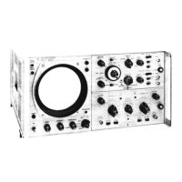
Model
141A
Section
V
Table 5-7
'I
1
i
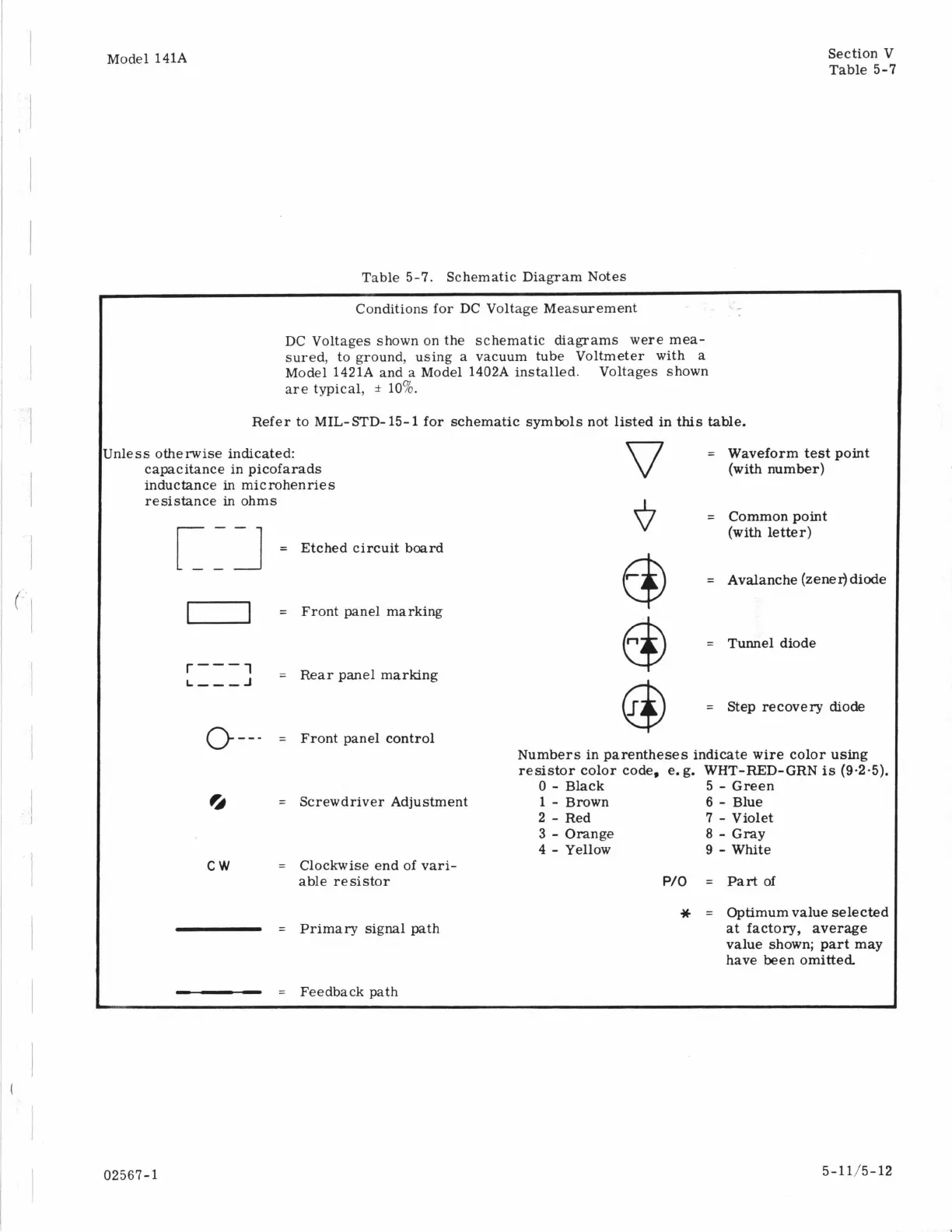
Table 5-7. Schematic Diagram Notes
Conditions for DC Voltage Measurement
DC Voltages shown on the schematic diagrams were mea-
sured, to ground, using a vacuum tube Voltmeter with a
Model 1421A and a Model 1402A installed. Voltages shown
are typical,
*
10%.
Refer to MIL-STD- 15-
1
for schematic symbols not listed in
this
table.
rnless otherwise indicated:
capacitance in picofarads
inductance
in
microhenries
resistance
in
ohms
=
Etched circuit board
r
--I
1
=
Front panel marking
'
=
Rear
panel marking
r---
L-,,J
0
-
-
-
=
Front panel control
a
=
Screwdriver Adjustment
cw
=
Clockwise end of vari-
able resistor
=
Primary signal
path
=
Feedback path
=
Waveform
test
point
(with number)
=
Commonpoint
(with
letter)
=
Avalanche (zener) diode
@
=
Step recovery diode
@
Numbers in parentheses indicate wire color
using
resistor color code,
e.
g.
WHT-RED-GRN
is
(9.2.5).
0
-
Black
1
-
Brown
2
-
Red
4
-
Yellow
5
-
Green
6
-
Blue
7
-
Violet
9
-
White
3
-
Orange
8
-
Gray
P/O
=
Part of
*
=
Optimum value selected
at
factory, average
value shown; part may
have been omitted.
02567-1
5-1 1/5- 12