Model
141A
e
Section
IV
Paragraphs 4-22 to 4-31
t
RECTI
F
I
ER
V602, V603
DOUBLER
HIGH VOLTAGE
TRANSFORMER
T601
OSCILLATOR
0602
1,
YI1-
8-3
II
(
(--'
-RECTIFIER
IC,
V604
<--I
,.---
1
id
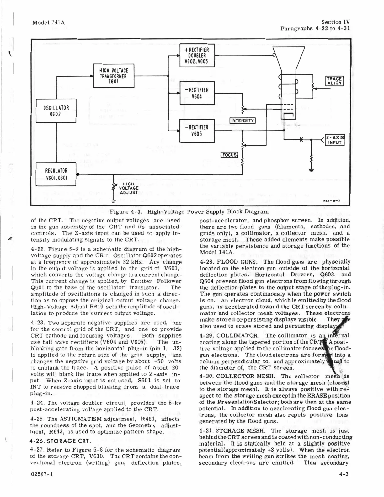
Figure 4-3. High-Voltage Power Supply Block Diagram
-RECTIFIER
V605
of the CRT. The negative output voltages
are
used
in the gun assembly of the CRT and its associated
controls. The Z-axis input can be used to apply in-
tensity modulating signals to the CRT.
4-22.
Figure 5-8
is
a schematic diagram of the high-
voltage supply and the CRT. Oscillator Q602 operates
at
a
frequency
of
approximately 32
kHz.
Any change
in the output voltage is applied to the grid of V601,
which converts the voltage change toa current change.
This current change is applied, by Emitter Follower
Q601,to the base of the oscillator transistor. The
amplitude of oscillations is changed in such
a
direc-
tion
as
to oppose the original output voltage change.
High-Voltage Adjust R619 sets the amplitude of oscil-
lation to produce the correct output voltage.
4-23. Two separate negative supplies are used, one
for the control grid of the CRT, and one to provide
CRT cathode and focusing voltages. Both supplies
use half wave rectifiers (V604 and V605). The un-
blanking gate from the horizontal plug-in (pin
1,
52)
is applied to the return side
of
the grid
supply, and
changes the negative grid voltage by about +50 volts
to unblank the trace.
A
positive pulse of about 20
volts will blank the trace when applied to Z-axis in-
put.
When Z-axis input is not used, S601 is set to
MT to receive chopped blanking from a dual-trace
plug-in.
4-24.
The voltage doubler circuit provides the 5-kv
post-accelerating voltage applied to the CRT.
4-25. The ASTIGMATISM adjustment, R461, affects
the roundness of the spot, and the Geometry adjust-
ment, R643, is used to optimize pattern shape.
4-26.
STORAGE
CRT.
4-27. Refer to Figure 5-8 for the schematic diagram
of the storage CRT, V610. The CRT contains the con-
ventional electron (writing) gun, deflection plates,
02567-1
11
post-accelerator, and phosphor screen. In addition,
there are two flood guns (filaments, cathodes, and
grids only),
a
collimator,
a
collector mesh, -and
a
storage mesh. These added elements make possible
the variable persistence and storage functions of the
Model 141A.
4-28. FLOOD
GUNS.
The flood guns
are
physcially
located on the electron gun outside of the horizontal
deflection plates. Horizontal Drivers, Q603, and
Q604 prevent flood gun electrons from flowing through
the deflection plates to the output stage of theplug-in.
The gun operates continuously when the power switch
is
on. An electron cloud, which
is
emittedbytheflood
guns,
is
accelerated toward the CRTscreenby colli-
mator and collector mesh voltages. These electrons
make stored
or
persisting displays visible
also used to erase stored and persisting
dis
4-29. COLLIMATOR. The collimator
is
coating along the tapered portion of the CR
tive voltage applied to the collimator focus
gun electrons. The cloudelectrons
are
fo
column perpendicular to, and approximately
the diameter of, the CRT screen.
4-30. COLLECTOR MESH. The collecto
between the flood guns and the storage mesh (closest
to the storage mesh). It
is
always positive with re-
spect to the storage mesh except
in
the ERASEposition
of the PresentationSelector; bothare then at the same
potential.
In
addition to accelerating flood gun elec-
trons, the collector mesh also repels positive ions
generated by the flood guns.
4-31. STORAGE MESH. The storage mesh
is
just
behindthe CRT screen and
is
coated withnon-conducting
material. It
is
statically held
at
a
slightly positive
potential(approximate1y +3 volts). When the electron
beam from the writing gun strikes the mesh coating,
secondary electrons
are
emitted. This secondary
4-3
REGULATOR
V601,0601
HIGH