2-5
Installing the Switch
Installation Procedure
1. Prepare the Installation Site
Be sure to follow the guidelines below to ensure proper operation when
installing the switch into a network:
■ Verify that copper and fiber cabling meets the requirements of the
“Cabling Specifications” in Appendix A.
■ Protect the switch from radio frequency interference emissions.
■ Use electrical surge suppression.
■ Use safe connections with no damaged cables, connectors or shields.
Installation Space Requirements
2. Verify the Switch Passes Self Test
Before mounting the switch, verify it is working properly by plugging it into a
power source and confirming that it passes self test.
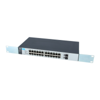
1. For the 1810-24 and 1810-24G Switches, connect the power cord supplied
with the switch to the power connector on the back of the switch, and
then into a properly grounded electrical outlet.
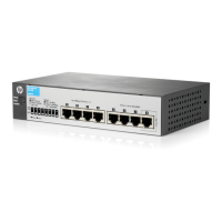
For the 1810-8 and 1810-8G Switches, connect the AC/DC adapter’s power
cord to the power connector on the back of the switch, and then plug the
AC/DC power adapter into a nearby properly grounded electrical outlet.
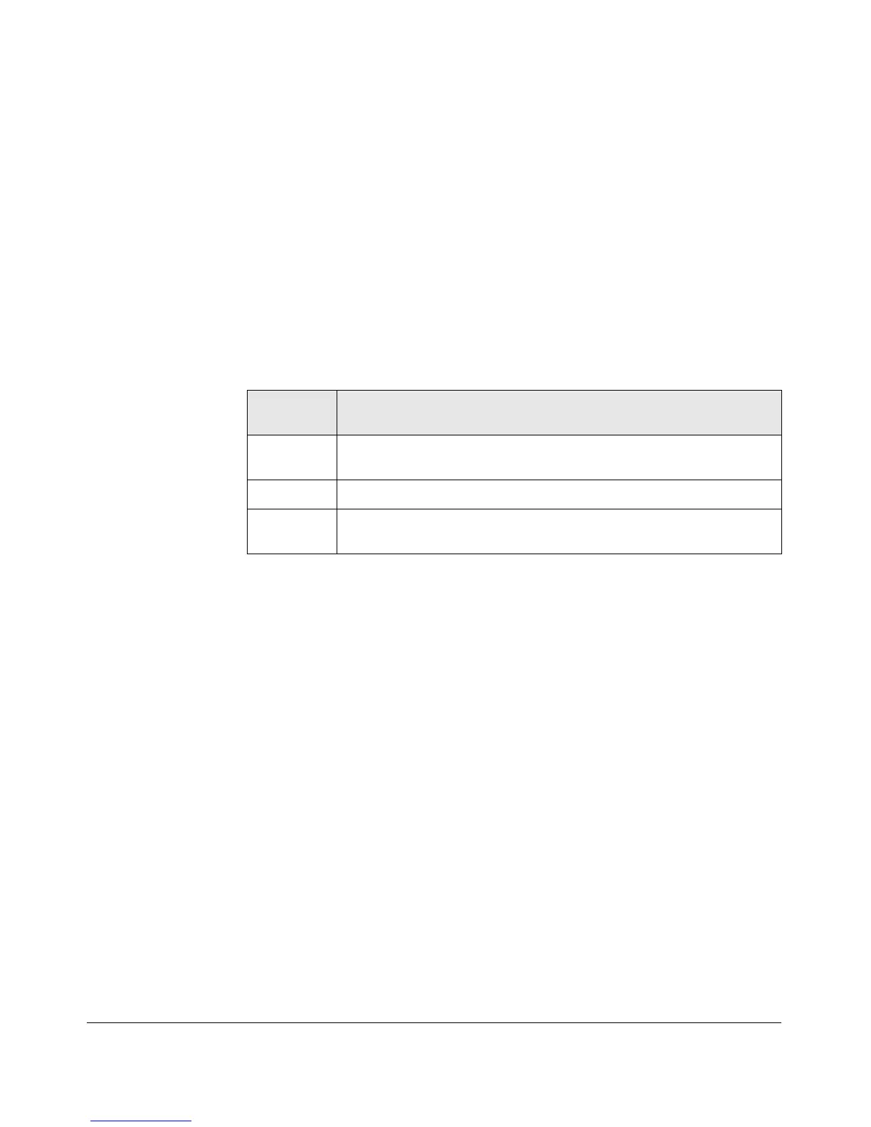
Switch
Orientation
Clearance Requirements
Front At least 7.6 cm (3 inches) of space for the twisted-pair and fiber-optic
cabling.
Back
At least 3.8 cm (1 1/2 inches) of space for the power cord and switch cooling.
Sides At least 7.6 cm (3 inches) for cooling, except if the switch is installed in an
open EIA/TIA rack.

 Loading...