Single-ended TDR Measurements
Establishing the Reference Plane and Normalizing
7-17
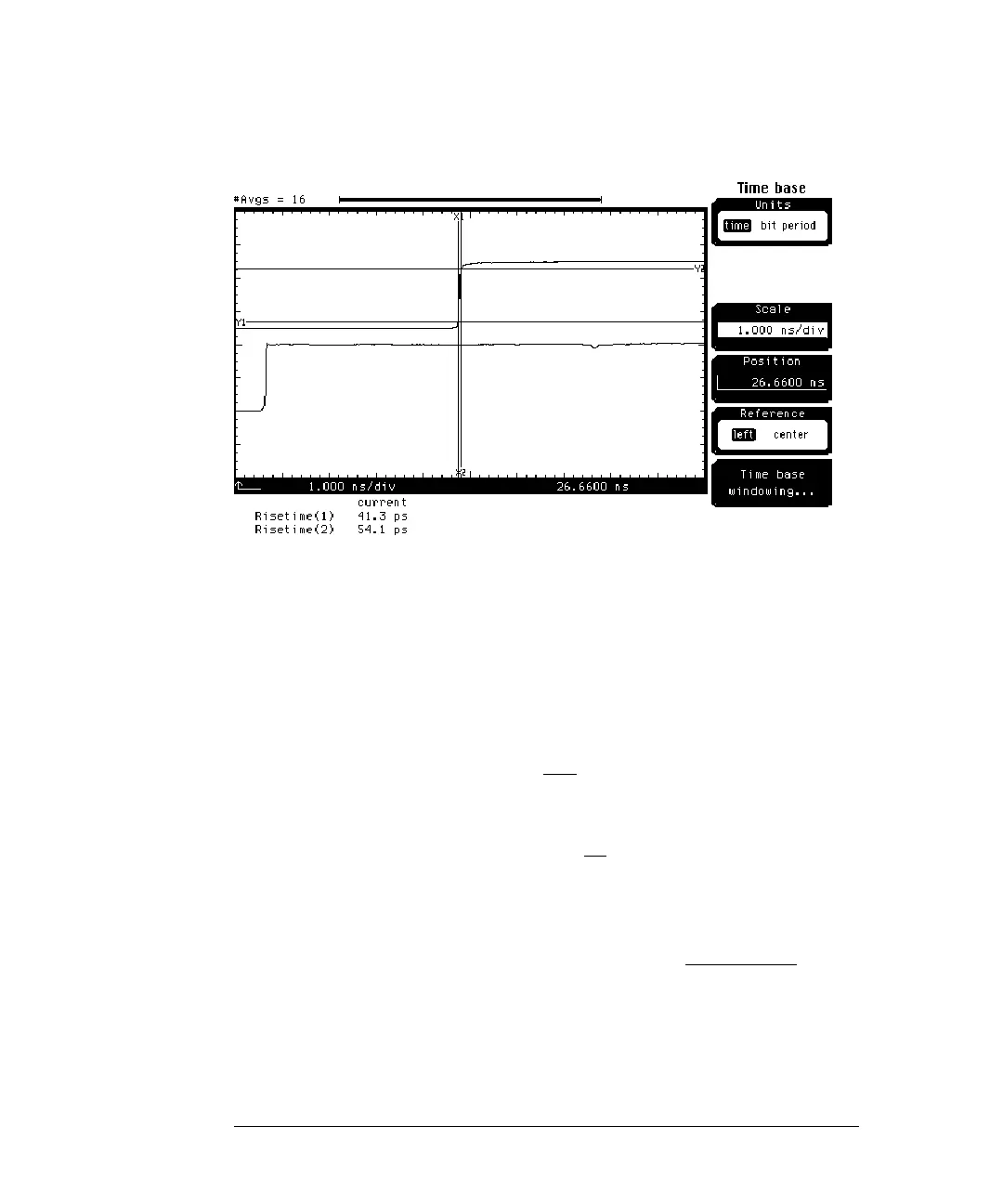
Figure 7-9
The risetime for channel 1 (incident step) is approximately 40 ps while the
risetime for channel 2 (received step) is greater than 40 ps. This is due to cable
and connector losses. We will now perform a TDT normalization.
1 Change the
Scale
to 500.0 ps/div.
2 Change the
Position
until the positive step on channel 2 is positioned at
the 3rd graticule from the left side of the display.
3 Press the
TDR/TDT Setup key.
4 Press the
Normalize response . . .
softkey.
5 Press the
TDR/TDT
softkey to select TDT.
6 Press the
Establish normalization & ref plane
softkey.
7 Press the
Continue
softkey.
8 Press the
TDT normalize
softkey to select on.
9 Press the
SETUP Channel 2/4 key.
10 Press the
Display
softkey to turn off channel 2 display.
11 Press the
blue key followed by the Clr key.
12 Press the
blue key followed by the 7 key and select response 2.
13 Press the
Enter
softkey.
14 Press the
TDR/TDT Setup key.
15 Press the
Normalize response . . .
softkey.