11-2
Introduction
Understanding the operation of transmission lines used in conjunction
with high speed MECL circuits is necessary in order to be able to
completely characterize system operation. This Chapter describes
transmission lines with respect to both line reflections and propagation
delay times. Also discussed will be the use of the Time Domain
Reflectometer (TDR) for measuring transmission line characteristics.
Transmission Line Design
A transmission line, as used with high speed MECL, is a signal path that exhibits
a characteristic impedance. Coaxial cables and twisted pairs have a defined
characteristic impedance and are commonly referred to as transmission lines.
Equally important, printed circuit fabrication of microstrip and stripline results
in closely-controlled transmission-line impedance.
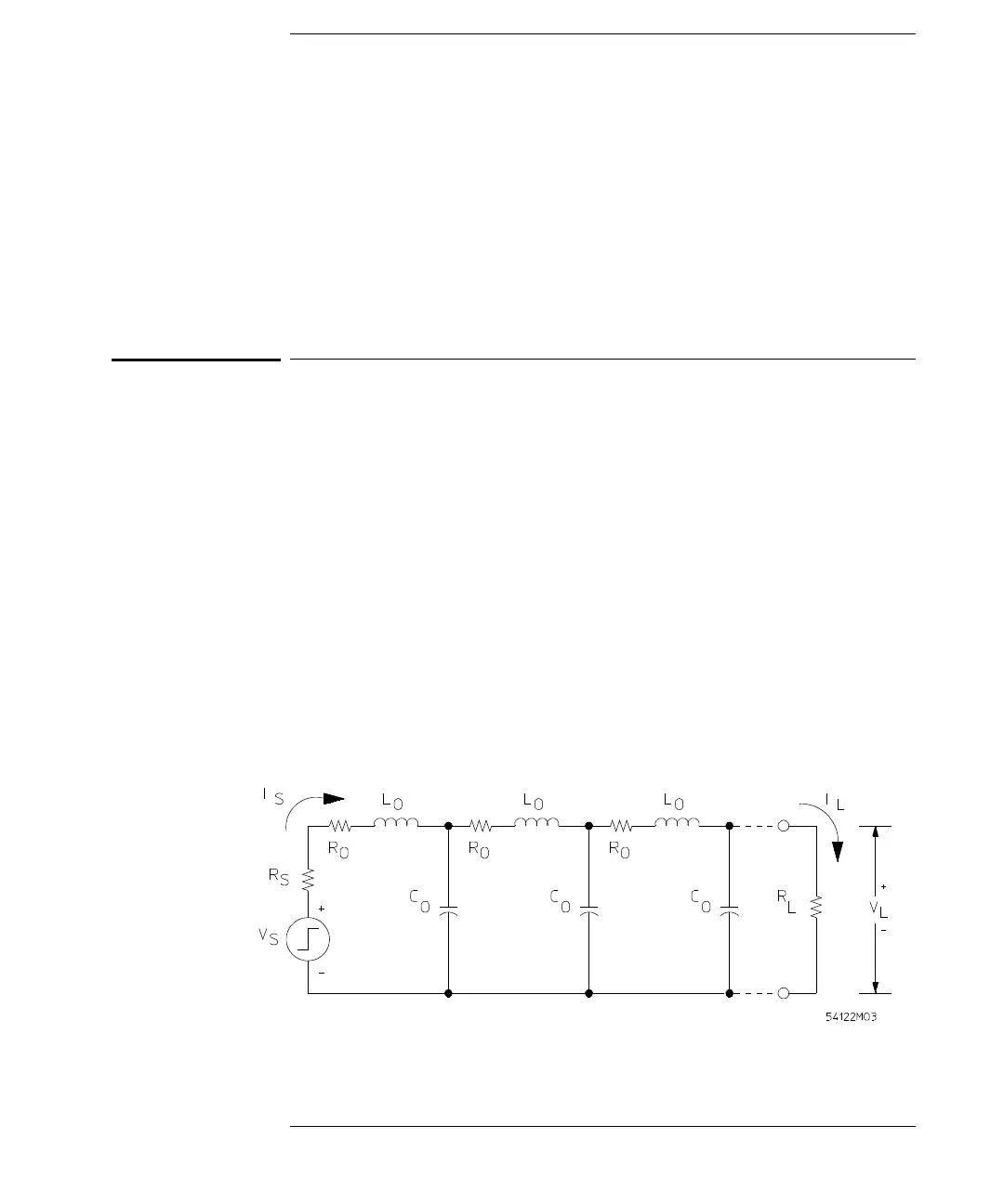
Transmission lines may be approximated by the lumped constant
representation shown in Figure 11-1. The effect of the line resistance R
o
, of the
line on characteristic impedance, Z
o
, is negligible, but it will cause some loss in
voltage at the receiving end of long lines. The inductance and capacitance of
the line in the presence of a ground plane are a function of the dielectric
medium, the thickness and width of the line, and the spacing from the ground
plane. The inductance and capacitance of the line can be measured using an
LC meter.
Figure 11-1
Equivalent Circuit of a Transmission Line