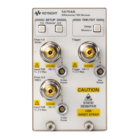
Differential TDR Measurements
Making Differential TDT Measurements
8-15
Making Differential TDT Measurements
This section will show how to deskew the TDR step generators, establish the
reference planes, and make differential and common mode TDT measurements.
To perform the tasks in this section, you need the following:
• 4 good quality SMA cables one meter in length, such as the HP 8120-4948
cable.
• 2 female-to-female SMA adapters.
• 1 each demo board (54754-66503) supplied with the TDR plug-in.
•1 SMA short.
• 1 SMA 50 ohm load.
• 1 HP 54754A TDR Module.
• 1 two channel electrical plug-in module, for example, an HP 54751A or
HP 83483A 20 GHz Module.
Deskewing Differential TDR Step Generators
The first thing that must be done before you can make differential TDT
measurements is to deskew the TDR step generators to the end of the cables.
The following steps describe the deskewing process.
1
Press the
STORAGE Setup
menu key above the display.
2
Press the
Default setup
softkey.
3
Press
TDR/TDT Setup
on the TDR plug-in module.
4
Press the
Stimulus
softkey and select
differential
.
5
Press the
Enter
softkey.
6
Press the
Preset TDR/TDT
softkey.
7
Press the
SETUP
Acquisition
menu key below the display.
8
Change the
# of averages
from 16 to 4.
If you have just completed the
Measuring Differential and Common Mode
Impedance
section, set the stimulus to differential and go to the
Deskewing the
TDT Channels
section.

 Loading...