TDR Fundamentals
Instrument Configuration
9-27
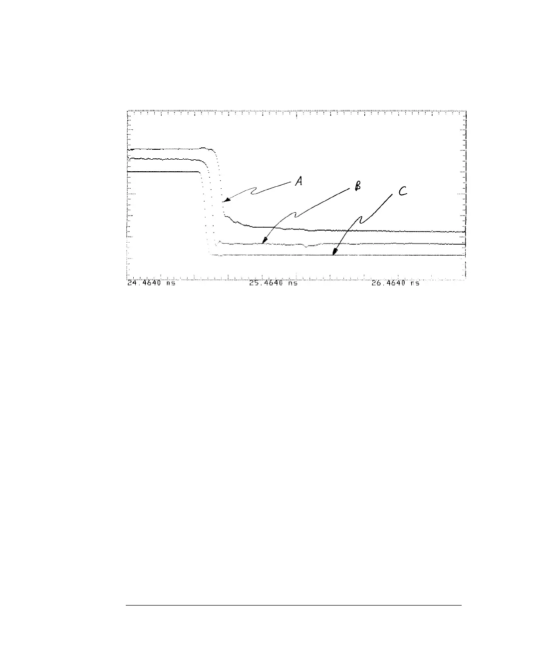
Figure 9-23
Short Cables (B) and Normalization (C) can Reduce the Effects of Cable Loss Seen in (A)
Multiple Discontinuities
Multiple discontinuities are another source of error in TDR measurements. A
discontinuity that occurs before the discontinuity of interest will cause a
degradation of risetime and accuracy of reflection measurements similar to
cable losses. Typically in a TDR system, if high accuracy and resolution are
needed to examine a particular discontinuity on a transmission line, the
reflections due to discontinuities that are before the one of interest must be
small. One example involves a transmission line with two discontinuities on it.
The first one has a maximum reflection coefficient of ρ
1
and the second of ρ
2
.
The percent error in ρ
2
due to ρ
1
is:
These results are computed values and are useful for estimating errors in
measurements. As with cable loss, you can remove the effects of multiple
discontinuities using normalization up to the point in the transmission line
where a calibration is done.
ρ
1
% error in
ρ
2
0.01 <0.25%
0.05 ~2%
0.10 ~6%