Improving Time Domain Network Measurements
Sources of Measurement Error
10-4
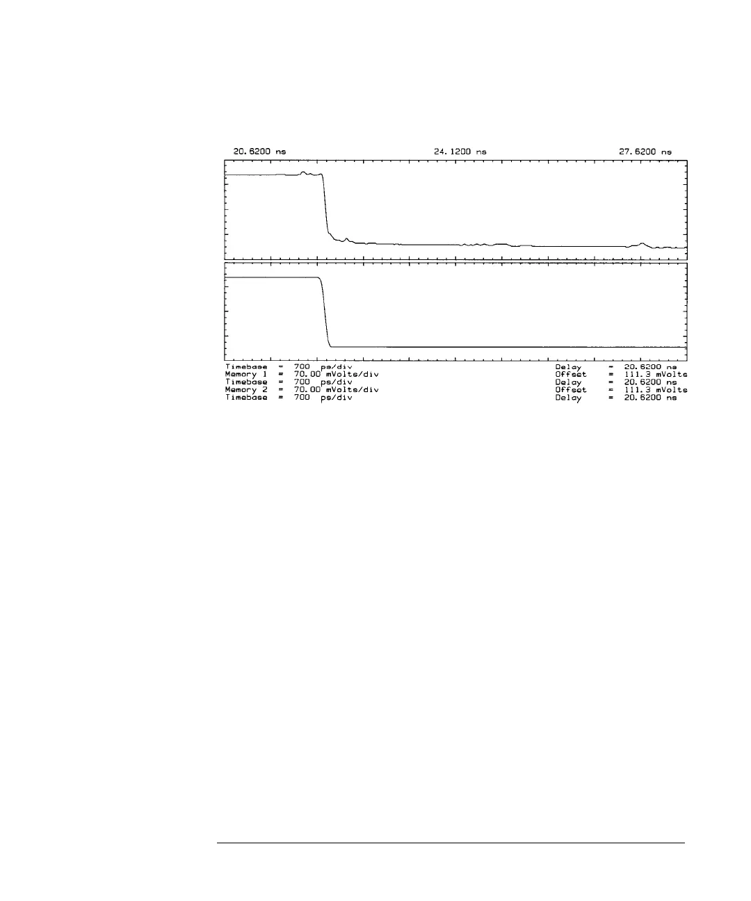
Figure 10-1
The top waveform shows distortions caused by cables and connectors. The bottom waveform
shows how normalization corrects for these distortions
The Oscilloscope as an Error Source
Oscilloscopes introduce errors into measurements in several ways. The finite
bandwidth of the oscilloscope translates to limited risetime. Edges with
risetimes that approach the minimum risetime of the oscilloscope are measured
slower than they actually are. When measuring how a device responds to a very
fast edge, the oscilloscope's limited risetime may distort or hide some of the
device response.
The oscilloscope can also introduce small errors that are due to the trigger
coupling into the channels and channel crosstalk. These errors appear as
ringing and other non-flatness in the display of the measurement channel
baseline and are superimposed on the measured waveform. They are generally
small and are only significant when measuring small signals.
The Step Generator as an Error Source
The shape of the step stimulus is also important for accurate TDNA
measurements. The DUT responds not only to the step, but also to the
aberrations on the step such as overshoot and non-flatness. If the overshoot is
substantial, the DUT's response can be more difficult to interpret.