Care and Handling of Precision Connectors
Mechanical Inspection
2-10
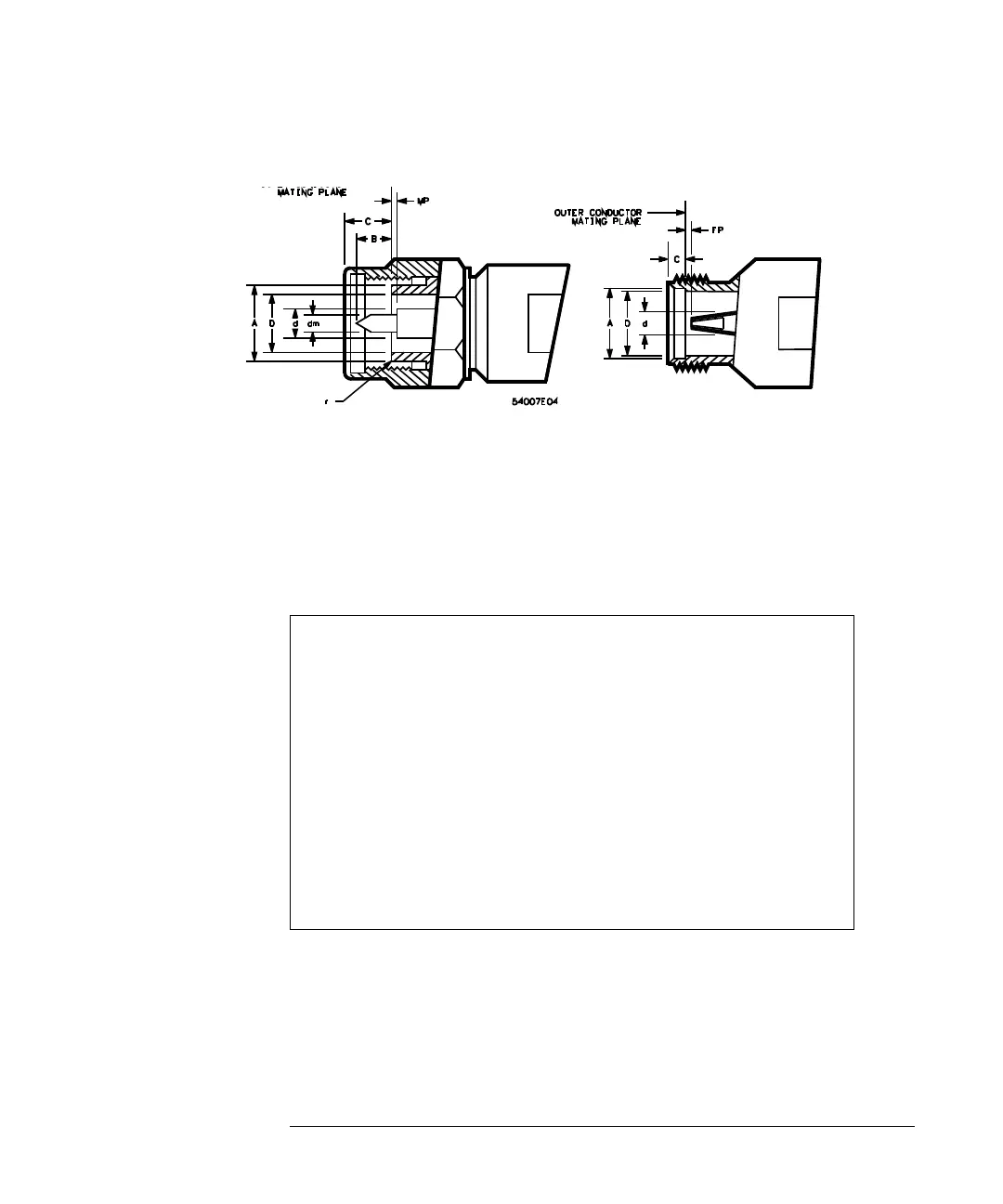
Figure 2-3
D = inside diameter of the outer conductor
d = diameter of male/female center connector
A = outside diameter of outer conductor at the mating plane
r = corner relief for male connector
B = protrusion of the male contact pin tip beyond the outer conductor mating plane
C = recession of the outer conductor mating plane behind outer face of connector
MP = recession of male contact pin shoulder behind outer conductor mating plane
Mechanical Dimensions of Connector Faces
Male Connectors Female Connectors
inches millimeters inches millimeters
D = 0.1378 ± 0.0005 3.500 ± 0.013 D = 0.1378 ± 0.0005 3.500 ± 0.013
d = 0.0598 ± 0.0003 1.519 ± 0.008 d = 0.0598 ± 0.0003 1.519 ± 0.008
A = 0.1803 + 0.000
- 0.002
4.580 + 0.00
- 0.05
A = 0.1807 + 0.002
- 0.000
4.590 + 0.05
- 0.00
r = 0.003 0.08 r = 0.003 0.08
B = 0.085 +0.005
- 0.015
2.16 + 0.13
- 0.38
N/A
C = 0.120 ± 0.015 3.05 ± 0.38 C = 0.176 ± 0.002 1.93 ± 0.05
Mp = 0.00 + 0.003
- 0.000
0.000 + 0.08
- 0.00
Fp = 0.000 + 0.003
- 0.00
0.000 + 0.08
- 0.00
dm = 0.037 + 0.000
- 0.001
0.94 + 0.00
- 0.03
N/A