Model
5526A
Flatness Measurements
SECTION 9
FLATNESS
MEASUREMENTS
CONTENTS
INTRODUCTION
OPERATING
SPECIF
I
CA
TIONS
HARDWARE
REQU
I
RED
RELATED
MEASUREMENTS
REFERENCE
MATER
I
AL
INSTAllATION
AND
AUGNMENT OF OPTICS
MEASUREMENT
DISPLAY
SETT
I
NGS
MAKING A
MEASUREMENT
WHAT
AFFECTS
ACCURACY?
INTRODUCTION
Flatness
deviation
ca
n
be
calculated from angle
information
from the Angular Optics and
from
the length dimensions of the Footspaclng
Pads
u
se
d. The HI) Dimensional
Metrology
Analysis
System
programs
cil
lculate and pl
ol
flatness data
for
this application.
These
measurements
are
be
st
suited for surface plates. since we u
se
the same
method
used
with
autocollimators (sometimes referred to 3S the
"Moody"
method
).
In this User's Guide
sec
tion (Section 9). we describe
how
to
se
t up
for
and make a Flal rH
!SS
measurement using the Angul
ar
Optics.
See
Appendix A for a description of the principles on
which this measurement
is
based.
OPERATING SPECIFICATIONS
The
following
speci
fi
ca
tions
assume
that
the optional Dimensional Metrology Analysis
System
is
used
in
co
njunction with the
HP
5528A
to
ga
Ther
, analyze and plot flatness
ca
libration results and
that
the temperature
of
all
optical components
is
stabilized in the range 15-25°C.
Values
do
not
include effects of surface cleanliness or operator
po
sitioning repeatability.
Accur
acy
: ±
O.2'
.\)
of displayed
va
lue.
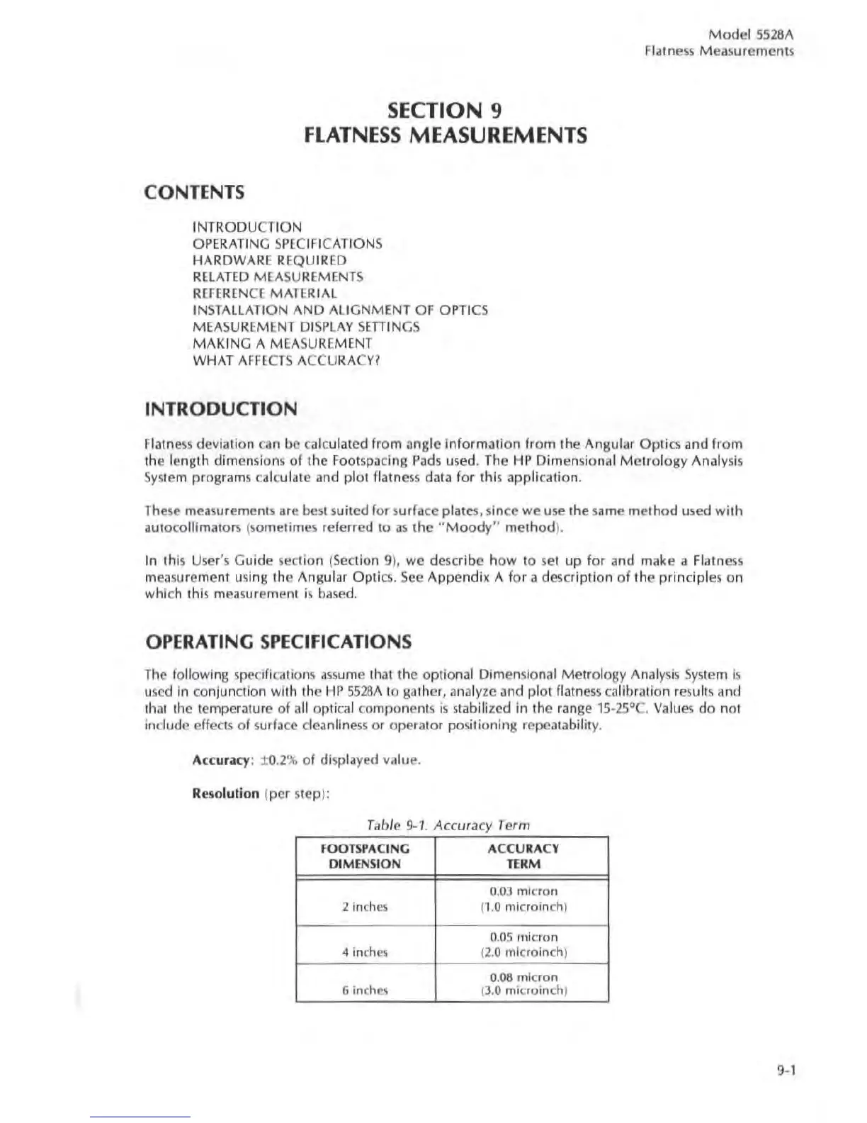
R
eso
lution (per step):
Table
9-1
Accuracy Term
FOOTSPACING
ACCU
RACY
DI
MENS
I
ON
TE
RM
0.
03
micron
2 inches p.O mlcroinch)
0.
05
micron
<I
inches (2.0 mlcroinch)
0.
08
micron
6
inches (
3.0
microinch
)
9-1