Model
5528A
Straightn
ess
and Squareness Con
si
derations
21·8
l
..
-.
.1
\
..-\
0,
\
\
\
,
'0-
-
-
-
-
-
i
-
-
0,
t
-
-
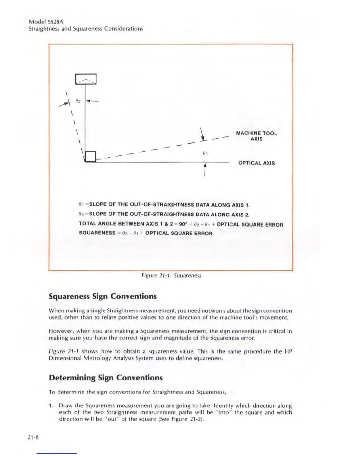
MACHINE TOOL
AXtS
OPTICAL AXIS
0,
- SLOPE
OF
THE
OUT
-OF-STRAIGHTNESS DATA ALONG AXIS 1.
0
2"'"
SLOPE OF THE
OUT·
OF-STRAIGHTNESS DATA ALONG AXIS 2.
TOTAL ANGLE BETWEEN AXtS 1 & 2 -
go
a +
02
-
0,
+ OPTICAL SQUARE ERROR
SQUARENESS -
82
- 0, +
OPTICAL
SQUARE ERROR
Figure
21
·
1,
Squareness
Squareness Sign Conventions
When making a single Straightness m
easu
rement, you need
not
wo
rry about the sign convention
used, o ther than
to
relate
po
sitive values
to
one d
ir
ection
of
the machine
too
l
's
mo
ve
ment.
However,
whe
n you are making a Squareness
measu
rement. the sign convention
is
criti
ca
l
in
making sure you have the correct sign and magnitude of the Squarcness erro
r.
Figure
21-1
shows h
ow
10
ob
t
ai
n a squaren
ess
va
lu
e.
This
is
the
sa
me procedure the
HP
Dimen
sional
Metrology
Anal
ys
is System
uses
to
define
squa
ren
ess.
Determining Sign Conventions
To
determine
Ih
e sign
co
nvention
s
for
St
ra
ightn
ess
and
Squa
ren
ess,
1.
Draw
the Squar
eness
measurement you are going to take. Identify
whic
h direction along
each
of
the
two
Straightness measurcment paths will be
"into"
the square and which
direction
wil
l be "O
UI
"
of
the
sq
uare (
See
Figu re 21·2
).