Model
5526A
St
raightness
Measurement
s (Along A H
or
i
zontal
Axis)
3. No adjustment
will
be
made to the l aser
Head
unless th e
adjustments
de
sc
ribed
in
step
"
1"
and
step " 2"
above
cause
the
BEAM
STRENGTH
indic
ator
to
mo
ve
into
the
"
red
" region.
If
this
happen
s,
you should rotate the
laser
head
untillhere
is
enough
beam
s
trength
, while
translating the
la
ser Head to keep
the
beam
centered
in
the
Int
erfe
rom
eter.
In
making any
adjustmenlto
the Laser
head
,
keep
in
mind that
the
Straightness
Opti
cs
appear
as
a plane mirror relative to
the
Laser Head. That is why you sh
ou
ld rot
ate
the
Laser Head
to
increase
beam
strength.
Procedure
1. Reset the Measurement Display with the Optics
at
the
near
end
of travel.
2.
Move the
ma
chine (and Optics) to the
fa
r
end
of travel and
note
the slope meas
urement
on
the
Measurement
Di
s
pla
y.
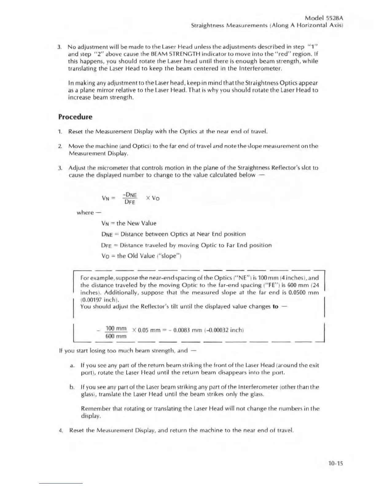
3. Adjust the
mi
crometer Ihat conlrols motion
in
the
plane of
the
Straightness
Refledor
's slot
to
cause the
di
spla
ye
d
number
to c
hange
to the value calculated
below
-
where -
X
Vo
VN
""
the New Value
DNE
=
Di
stance between Opti
cs
at
Near
End
position
DFE
""
Distance traveled by moving
Optic
to
Far
End position
Vo
= the Old
Va
lue ("sl
ope"
)
~example
,
s
uppo
se
the
near
-e
nd
spacing of the
Opti
cs ("NE")
is
100
mm
(4 inches
),
and!
I
~~
~
hdi
s
tance
tra
ve
led by the moving
Opli
c to
the
far-end spacing ("
FE
" ) is 600
mm
(24 1
in
ches). Additionally, s
uppo
se thai the measur
ed
sl
ope
at
the far
end
is 0.0500
mm
(0.00197
in
ch
).
You
should adjusl the Reflector's tilt until
the
displayed value changes 10 -
L
-
100
mm X 0.05 mm = - 0.0083
rnrn
HUX)032
in
ch)
600
mm
----
---
--
--
If
you start losing too much
be
am
st
rength,
and
-
_J
a.
U you see
an
y part of the return
beam
st
rikjn~
the front of the
La
ser Head (around the ex
it
port
),
rotate the
la
ser Head until the return beam
di
sappears into the port.
b.
If you s
ee
any part of the
la
ser
beam
striking any pat! of
the
Interferometer (other than
the
glass), translate the laser Head until
the
beam strikes only
the
glass.
Rememb
er
Ihal rotating or translaling
the
La
ser H
ead
will
no
t chan
ge
the
numbers
in the
di
spla
y.
4. Reset the Measurement
Di
spla
y,
and return
the
machine to the near
end
of travel.
10·15