Model
5528A
Straightness
Mea
su
rements
11
-10
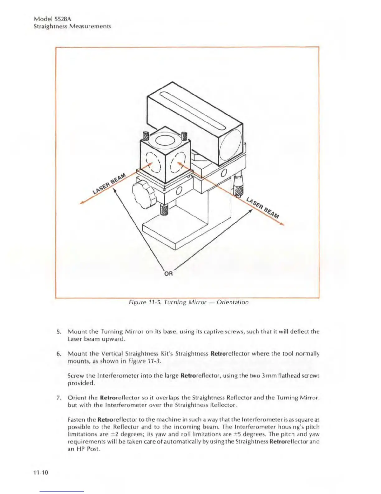
Figure 11-5. Turning
Mirror
- Orientation
5.
Mount
the
Turning Mirror
on
its
ba
se,
usinS its captive screws, such that II
will
deflect the
la
ser
beam
upward
.
6.
Mount
the
Vertical Siraishtness
Ki
t's Straightness Retroreflector
where
the
tool normally
mounts
,
35
shown
In
figure
11-3.
Screw
the
Interferometer
into
the
large Relroreflector, usinS the two 3 mm flathead screws
provided.
7.
Orient
the
Retr
orefle
c
lor
so
it
overlaps
thc
Straightness Reflector
and
the
Turning Mirror,
but with
the
Interfero
meter
over
the
Straightness Reflector.
Fasten
the
Re
lr
orcf
l
cctor
to
the ma
ch
ine
in such a way that the I
nterferometer
is
as
square
as
possible
to
the
Reflector
and
to
the
incoming beam. The Interferom
eter
housing's pitch
limitations are
.±
2
degrees;
its
yaw
and
roillimit31ions are ±5
degree
s.
The pitch and yaw
requirement
s will be taken care
of
aUlOmalically
by
using the Straightness Rclrorefleclor and
an
HP
Post.