Model
5528A
Straightness
Measurements
Alignment Pro
ce
dur
e
(Fo
r Hori
zo
ntal
Or
Vertical A
xis
)
1. Select the exit
port'
s large aperture.
2.
You
are
now
ready to align the
La
ser
to
the
machine
's travel.
Review the " GUNSIGHT" method
of
alignment
in
Se
c
tion
15
of
this User's
Guide
.
Your goal
is
to adjust the
la
s
er
Head
to
track the
Optic
's
progression
along
the travel path.
while
maintaining the beam's near-end-of-travel position. You
will
do
this by -
• Keeping the beam in the ring
on
the Re
lr
oreflector
,
to
maintain
the
beam'
s near-
end-
of
travel
po
s
ition
, and '-
•
Keeping a
two
-
dot
pattern in
line
with
the
jun
c
tion
of
the Reflec
tor'
s
mirrors
, and
symmetrical about
its
s
lotted
opening,
to
match the
Opti
c's travel.
This will be a
little
different
than aligning
for
Distance and Angular measurements, since
with
these alignments you were only watc
hing
one
dot
relative to a target crosshair.
3.
Move
the Optics to the far end
of
travel.
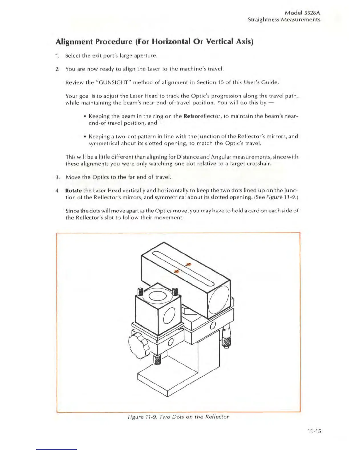
4.
Rotate the laser Head vertically and
horizontally
to
keep
the
two
dai
S
lined
up
on
the
jun
c-
tion
of
the Reflec
tor
's
mirrors, and s
ymmetri
c
al
about
its slotted
opening.
(
See
Figure 11-9.)
Sin
ce the dots will move apart
as
the Optics move, you may have to
hold
a card
on
ea
ch side
of
the Reflector's slot to
follow
their
movement
.
Fi
g
ur
e
11
-9. Two DaIS on
Ihe
Reflector
11
-
15