Model
5528A
Squareness
Mea
s
ur
e
ment
s (In A
Horizontal
Plane)
6.
Sec
ure the
Interferometer
to the machine in such a way that the
Interferometer
is
as
sq
uare
as
possible relative to the incoming beam. The
Interf
e
rom
eter housing's
pit
ch
limitations
are
±2
degrees; its yaw and roll limitations are ±5 degrees. The
pit
ch
requir
e
ment
will
be taken
ca
re
of
automatically by using the
mounting
hardware
listed above.
7.
Make
s
ure
the Optical
Squa
re is fairly square relative to the machine and
to
the
I
nterferometer
, and then
sec
ure it
to
the
machine.
8.
Select the small opening
for
the laser
Head'
s exit
pan,
and
se
t the
turr
et
ring
to
"O
THER
".
(
When
aligning
your
se
tup
, it is good practice
to
work
with
the
st
rongest possible b
ea
m,
which
this
se
llin
g provides. )
9.
Attach the target to the Straightness I
nterferometer.
This tar
ge
t is
included
with
the Optics.
The target s
hould
be attached to the Straightness
Interferometer
opening
that
is
directed
toward the
Laser
Head.
Make
sure the target
is
p
osi
tioned
as
closely
as
po
ss
ible
relative to the edges
of
the
Optic.
Usc
your
fingers to match edges.
10.
Visually align the
La
ser Head
as
well as
yo
u
ca
n paral
lc
l to the
dire
ct
ion
of travel and
po
s
ition
it
so
its beam enters via the hole in the
middle
of
the
Interferometer'
s target.
Use
"Autoreflection"
to help you
do
this o nce you
become
proficient
at
la
se
r System
measurements.
11.
Rotate the Interferometer's
bezel
until
the beze
l'
s scribe
line
is
or
iented
90
degrees
to
the
Optical Square's slot. Two
beams
s
hould
now
co
me
out
of
the
Interferom
ete
r, in a plane
perpendicular
10 the Optical Square's slo
l.
1
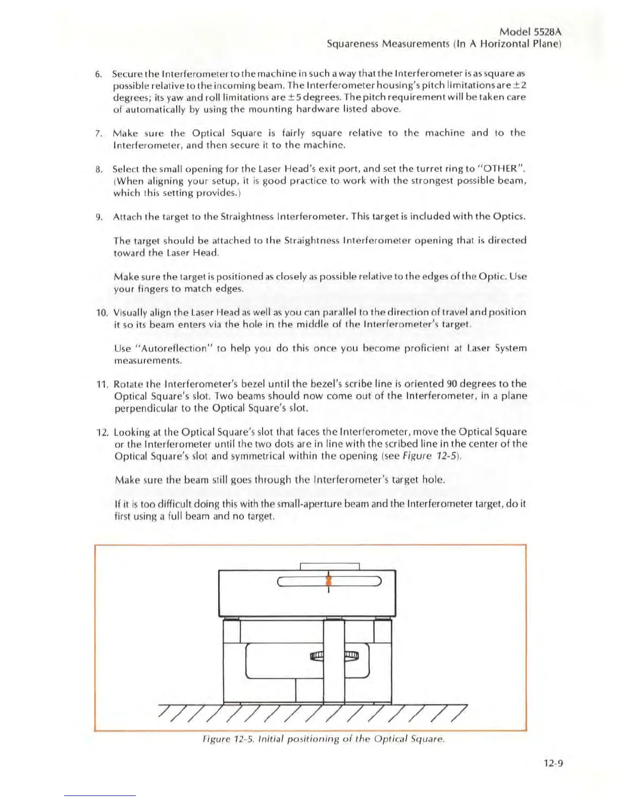
2.
Looking
at
the Optical Square's s
lot
that
faces
the
Interf
erome
ter.
move
the
Optical
Square
or
the Interferometer
until
the two dots arc in
line
with
the
sc
ribed
line
in
the
ce
nter
of
the
Optical Square's slot and symmetri
ca
l
within
the
opening
{
see
Figure 12-5).
Make
sure the beam still goes through the
Interferometer
's
target hol
e.
If
il
is
too difficult doing
Thi
s with
The
small-ape
rture
beam and the Interferometer target,
do
it
first using
a full beam and no tar
ge
t.
Figure 12-5. Initial
po
s
iUoning
of
the
Optical
Square.
12-9