Model
552
8A
Squiueness
Mea
s
urement
s (
In
a Vertical Plane )
12.
Se
t
th
e l aser Head's turret
rin
g to
"S
TRA
I
GHTNESS
",
and sel
ec
t
th
e small
ape
rture for
the
ex
it
po
rI.
(
You
can
also
do
this us
in
g the
full
beam
from the large aperture.)
1
3,
Translate the
la
ser Head ho
ri
zonta
ll
y
so
that
'h
e beam strikes
the
threaded
p
ort
on
th
e s
id
e of
the
Optical Square facing the
la
ser Head.
14.
Pl
ace the gage
bl
ock over the thre
aded
port
so
that
th
e b
eam
is refl
ec
t
ed
back towards the
l aser H
ead
(see
Fi
gure 13-
6;)
).
Use
a
rubber
band to secure the gag
eb
lock.
15.
ROlat
e the Optic
al
Square so that
the
re
fl
ected
b
eam
mikes
th
e
la
ser H
ead
and
is
c
entered
verti
ca
ll
y
on
it
s exit porI.
NOTE
If you Cilnnot pos
iti
on
th
e Optical Square u
si
ng
the
re
fl
ec
t
ed
beam,
mount
an indic
ator
in
the spindle and move the table
along
the
hori zontal
axi
s.
Ro
tat
e the Opti
ca
l
Sq
uare so that
ilS
sides arc parallel to the dir
ec
ti
on of
tr
avel.
16. Secure
th
e Opli
ca
l Square
in
this location.
1
7.
Translate the
la
ser Head horizontally so that the
beam
strikes the
ce
nter of the Turning
Mirror's
opening.
Use
the Intcrferom
ete
r
's
target
or
a
pi
ece
of
paper
to help you
do
thi
s.
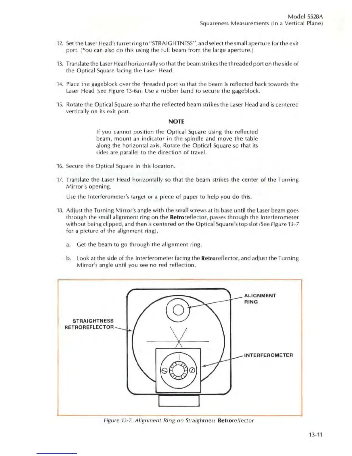
18.
Ad
jusl the Turning Mirror
's
a
ngl
e with
the
small screws at
il
s base until
the
la
ser
bcam
goes
th
rough the sma
ll
alignment ring on
the
Relrore
fl
ecto
r, passes t
hrough
the I
nt
erf
eromete
r
wit
hout being
dip
p
ed,
and
th
en is
cen
tered
on
the
Optical Square's
top
slot (Sec Figure
13
-7
for a
pi
cture of
th
e alignment
rin
g
).
a.
Get the beam to go through the alignme
nt
rin
g.
b, look
at
the side of the Interferom
ete
r facing the Rel
ror
e
ff
ec
t
or,
ilnd adjust the Turning
Mirror's
iln
gle until you see no red re
fl
ec
tion.
ST
RAI
GH
TNESS
RETRO
REFlE
CTOR
~"""
.
I
y
ALIG
NM
ENT
RING
INT
ERFEROMETER
Figure
13-
7.
AliSflm
enr
Ring
Oil
Straight ness Rc
tr
or
cf
lecfor
13-11