Model
5528A
Alignment Techniques
15-4
OVERLAPPING
DOTS
METHOD
This alignment method is u
se
d only for
Di
sta
nce or Velocity measurement
s.
Description
The
"Ove
rlapping Ool
s"
method
is
identi
ca
l 10 the
"Gunsight"
method, except that the Inter-
ferom
e
ter
and Retroreflecl
or
largets are removed and the
La
se
r Head return
pori
becomes the
target.
Procedure
1.
Install the Optics
as
described in Section 6 of this
Use
r
's
Guide (
"0
1
5T
ANCE
MEASUREMENTS
").
The
return
beams
from
yo
ur
Distance
Opti
cs
should co
mp
letely overlap
on
the
la
se
r Head
's
lo
wer
(return) port. The Optics sho
uld
be
at
the
"near
end of travel" ,
NO
TE
You should not
ha
ve
targets in plac
e.
2.
Move
the
Ret
r
oref
lector away
from
the
la
ser (or
se
parate the Optics).
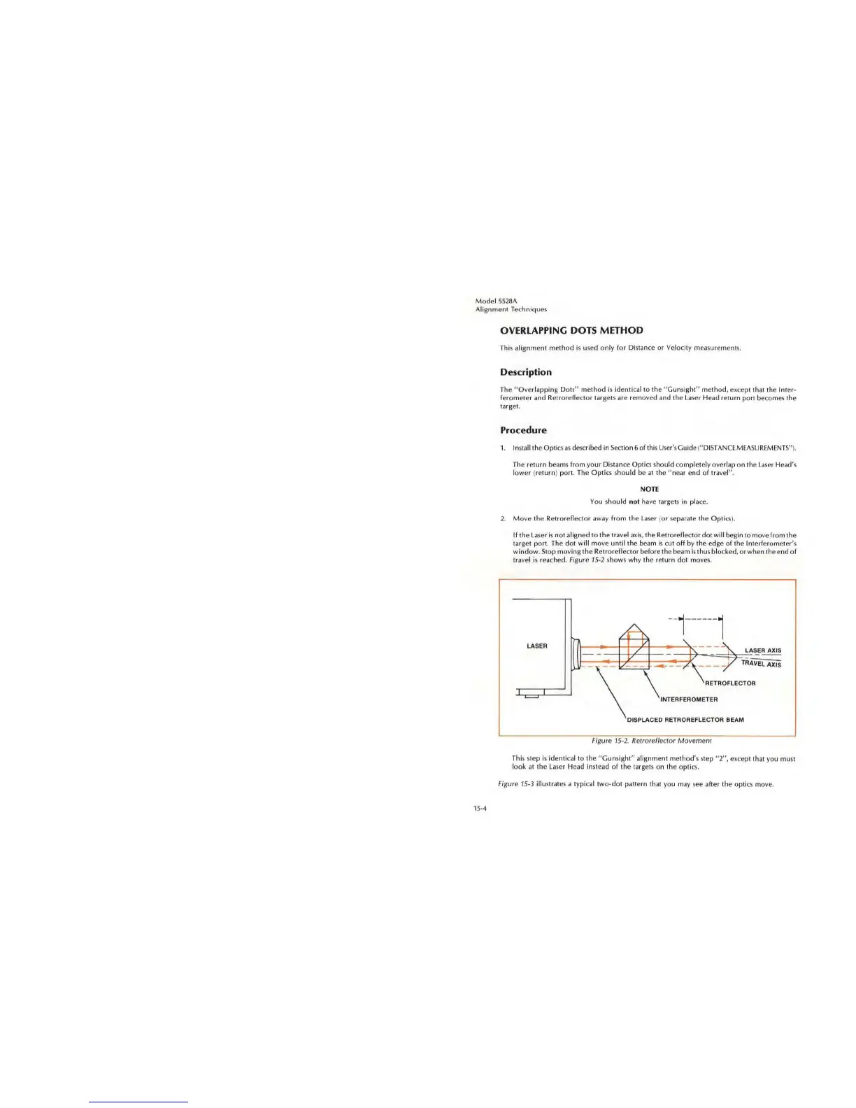
If the
La
se
r is
not
aligned
to
the
travel
axis,
the Retroreflector
dot
will
begin to move from the
target
port
. The
dot
will
move
until
the beam is cut
off
by the edge
of
the Interferometer
's
window,
Stop
mo
ving the Retroreflector before the beam is thus blocked, or when the end
of
travel is reached.
Fi
g
ur
e
15
-2 shows why the
re
turn dot moves .
LAS
ER
LA
SE
R A
XIS
'\
_ _ _ TRAVEL AX,S
RETROFLECTOR
--_
.
~--
INTERFEROMETE R
DI
SP
LACED RETR OREFLECTOR BEAM
Figure
15
-2. Relroreflec!or
Movemen/
This step is
identi
ca
l to the
"G
uns
ight"
alignment method
's
step
"2",
ex
cept that you must
l
ook
at
the
La
se
r H
ead
instead
of
the tar gels on the opti
cs.
Fi
g
ure
15
-3 illustrates a typical
two
-dot pattern that you may
see
after the
opti
cs
mov
e,