ModelS528A
Alignme
nt
T
ec
hnique
s
~
~~
0
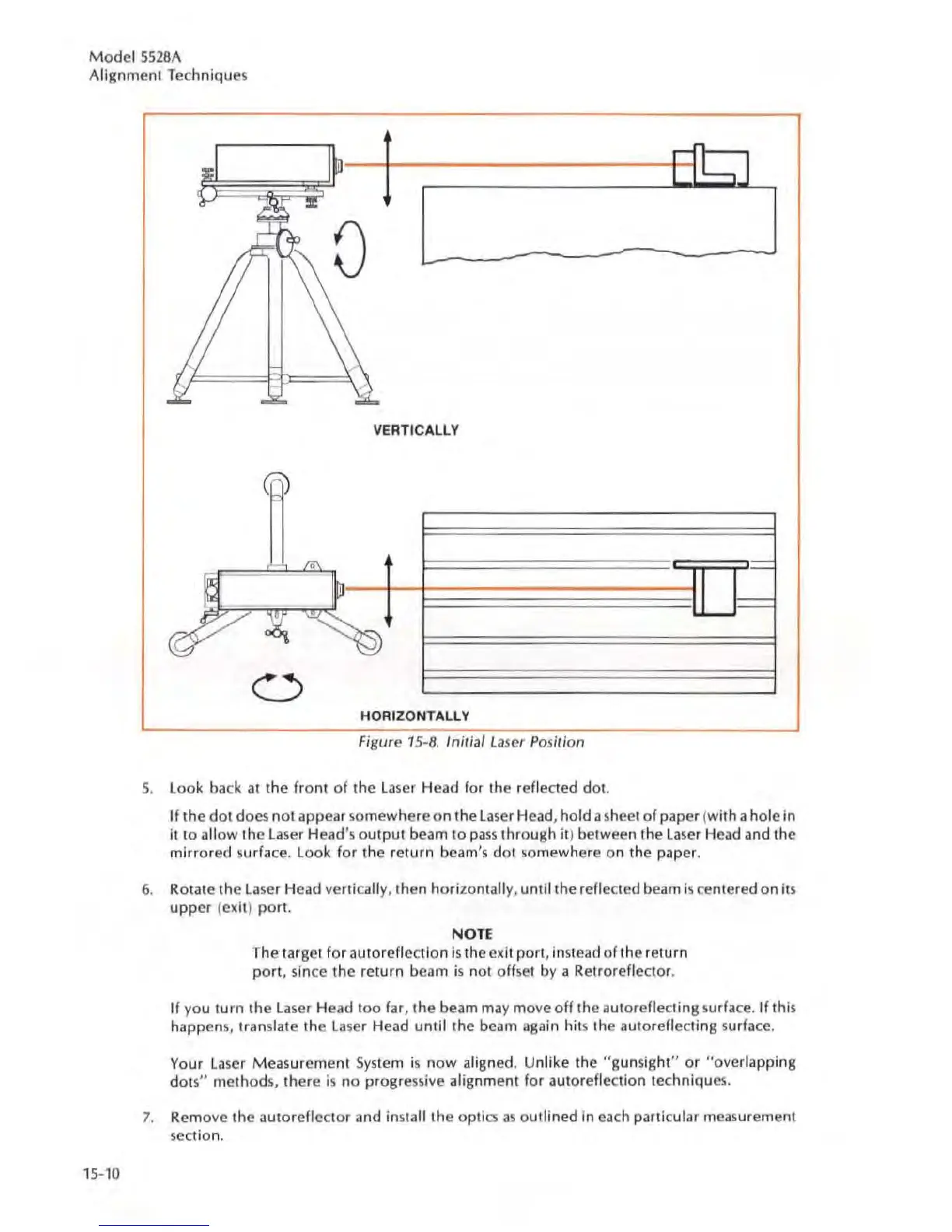
VERTICALLY
/0\
I
I'
HORIZONTALLY
Figure
15
-8. Initial
La
ser
Po
sir;on
S.
look
back at
the
front
of
the
la
ser Head
for
the reflected dol.
,-
'===
If
the
dot
docs not appear somewhere
on
the
laser Hcad, hold a sheet of
paper
(with a holc in
it to allow the
laser
Head's
output
beam to
pass
through
it)
between
the
la
se
r Head and
the
mirrored surface. Look for the return beam's dot somewhere on the paper.
6.
ROiale
th
e
la
ser Head vertica
ll
y,
then
horizontally, until the reflected beam is centered on
it
s
upper
f
elCh
) porI.
NOTE
The target for auto reflection
is
the
elCit
pori,
in
stead of
the
return
port, since
the
return bcam
is
not offset
by
a Retroreflector.
If
yo
u turn
the
las
er Head too far,
the
beam may
mo
vco
ff
the
autorcflecling
su
rfa
ce.
If
this
happen
s,
translat e
the
la
ser Head until
the
beam again
hit
s
the
aUlorefiecling surface.
Your
la
ser Measurement
Sys
tem
is
now aligned. Unlike the "gun sight"
or
"overlapping
dot
s"
method
s,
there
is
no
progressive alignment for autoreflectfon tcchniques.
7.
Remove
the
autoreflector and install
the
optic;
a5
outlined
In
each particular measurement
section.