Model
5528A
HP-IB
Information
d.
Slide the top cover rearward and remove it,
Figure
18
-1
s
how
s the location
of
the T ALK-
ONL
Y I
ADDRESSABLE
sw
itch,
on
the
top
of
the
top
printed
circuit board. toward the
front
of the
unit
.
e.
The T
ALK
-
ON
L Y I
ADDRESSABLE
switch
is
the seco
nd-from
-Ihe-Ieft
sw
itch
in
the eight-
switch assembly, and
is
labelled
on
the
printed
-circuit board.
Slide this switch to
its
TA
LK-ONLy ("1
")
position.
f.
Repl
ace
the Measurement Display unit's
top
cover and tighten the screw that secures it.
2.
Connect the Measurement Display
uni
t to the Pr
inter
, using
an
HP
-IB cable.
The
HP
Part
Number
for a typi
ca
l cable u
se
d here begins " 10833", and
ha
s a
lett
er suffix
"A",
" A
",
"C",
or " D
",
that indicates its length,
as
s
hown
in Table
18
-2.
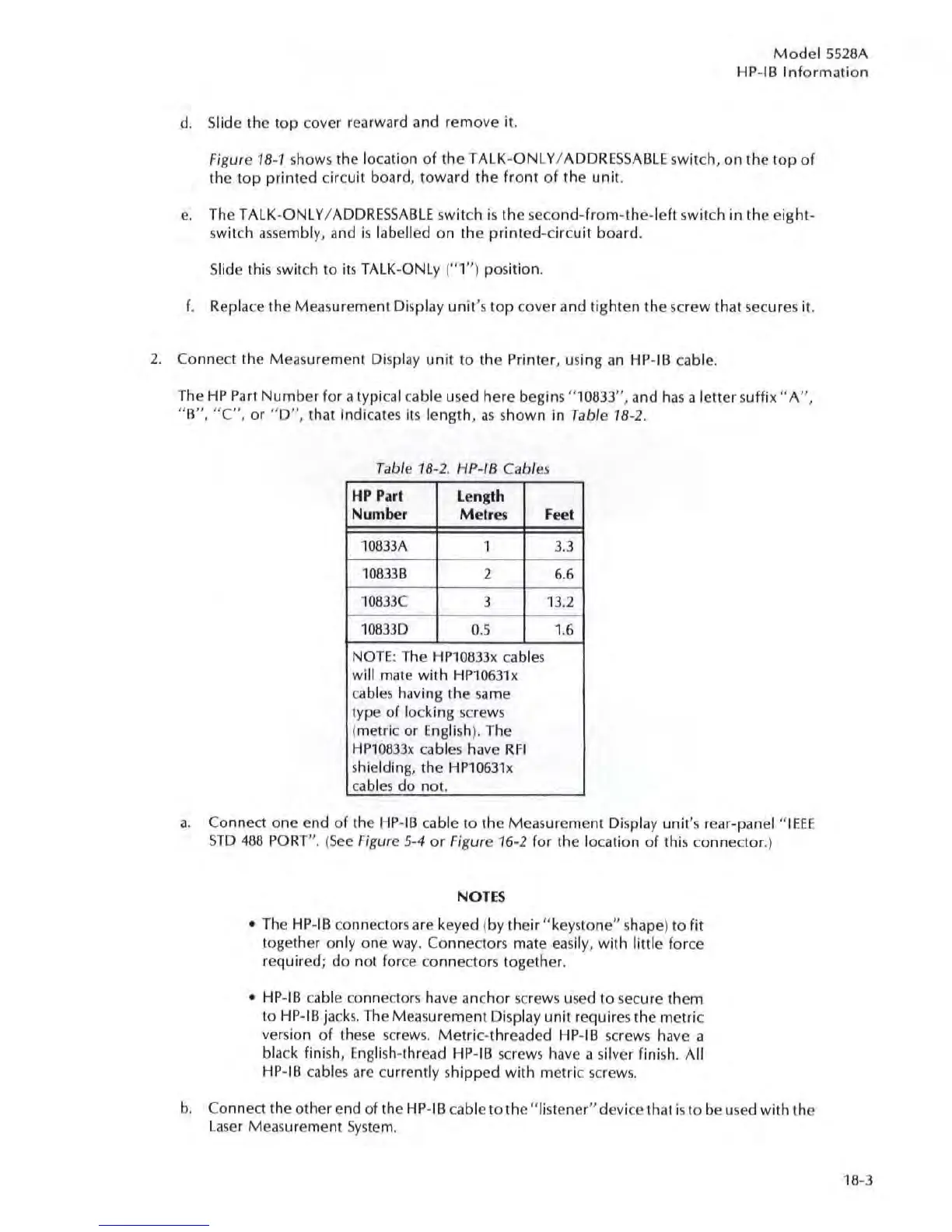
Table
18
-2 HP-IB Cabl
es
HP
P.
ut
Length
Number M etr
es
Fee'
10833A 1 3.3
10833B 2 6.6
10833C
3
13
.2
1083
30
0.5 1.6
NOTE
: The
HP
1
08
33x
ca
bl
es
will mate with
HP10631x
cables having the same
type of locking
sc
r
ews
(metric or English). The
HP10033x
cables have
RF
I
shielding, the
HP10631x
cabl
es
do not.
a.
Co
nnect one end of the HP-
IB
cable
10
the Measurement Displ
ay
unit
's
rear-panel "
IEEE
STD
468
PORT
".
(
See
Figure 5-4
or
Figure 16-2 for the lo
ca
tion
of
this connector.)
NOTE
S
•
The
HP
-IB connectors are keyed (by their
"keystone"
shape) to fit
together only one
way.
Connectors mate
eas
ily, with little
fo
rce
required; do not for
ce
connectors together.
•
HP
-IB
ca
ble connect
ors
have anchor
sc
rews u
se
d
to
secure them
to
HP-IB jacks. The Measurement Display unit requires the metric
vers
ion
of
these
sc
r
ews.
Metri
c-threaded HP-IB
sc
rews have a
bl
ack
finish, English-thread
HP
-
IB
sc
rews have a silver finish.
All
HP
-
IB
cab
l
es
are currently shipped with metric
sc
rew
s.
b.
Conne
ct
the other end of the HP-IB cable to the " listener" devi
ce
that is to be u
se
d with the
La
se
r
Me
as
urement
Syste
m.
18
-3