Mode
l
5528A
Appendi
x A: Principles of
Operation
ANGULAR
INTERFEROMETER
ANGULAR
REFLECTOR
BEAM BENDER
-------.
/
"
"-
IY
~
fl
±
~f1
1/
"
/
.,
"
/
"
"-
FROM LASER
V
~
'2
±.1
'2
'1
±~
'
1
f2
±M 2
TO
PHOTO DETECTOR
1/
/
Figure A-3.
An
gu
lar Mea5l/fcmcnls
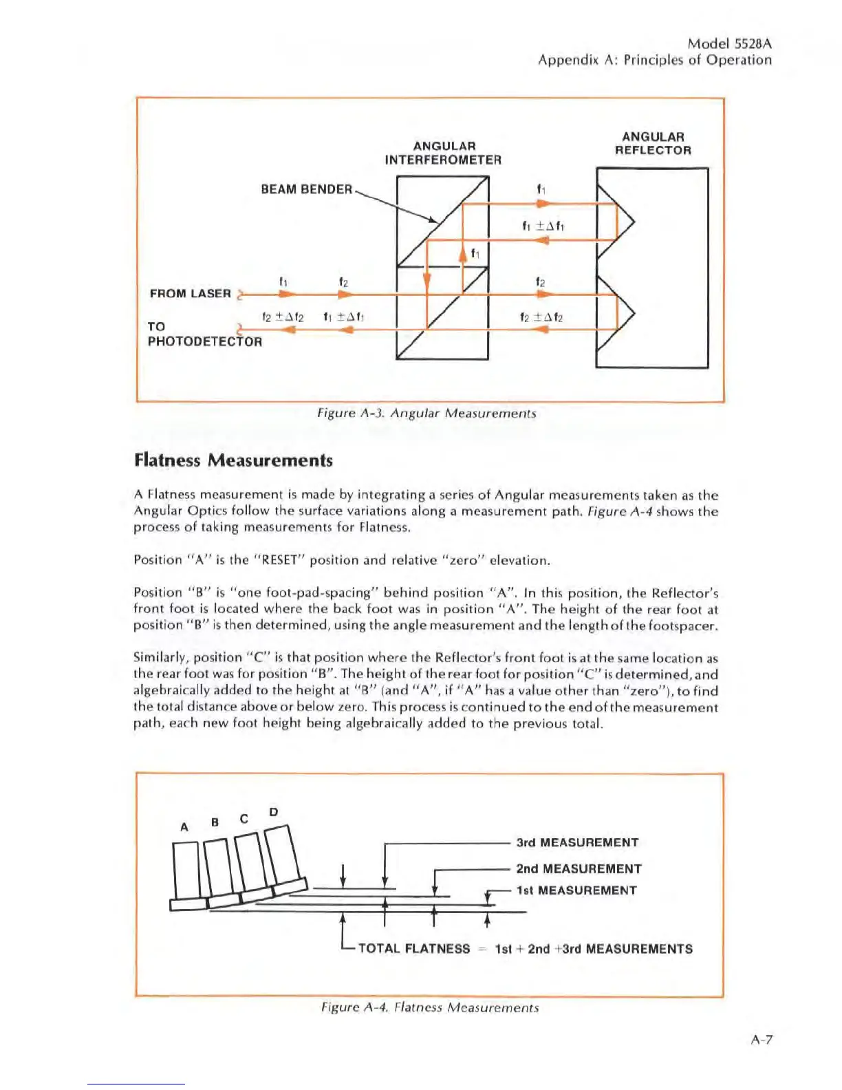
Flatness Measurements
A Flatness
mea
surement is made
by
integrating a
se
ries
of
Angular measurements taken
as
the
Angular
Optics
follow
the surface
va
riations along a measurement path. Figure
A-4
shows
the
process of taking
mea
surements for Flatne
ss.
Position
"A"
is the
"RES
ET
" position and relative
"ze
r
o"
elevation.
Po
sition
"B"
is " one foot-pad
-s
pacing"
behind
po
s
ition
"A".
In
Ihi
s position, the Reflector
's
front
foot is located where the back foot
was
in positi
on
"A"
. The height
of
the rear
foot
at
position " B" is then determined, using
the
angle
meas
ur
ement and the length
of
the foolspacer.
Si
milarly, position "e" is that position
where
the Reflec
tor
's
front
f
oo
t is at the
sa
me location
as
the rear
fOO
l
was
for position
"B".
The height
of
the rear
fOOl
for
position
tiC"
isdetermined
, and
algebraically added to the height
at
li
B"
(and " A
",
if
"A"
ha
s a
va
lue
other
than
"ze
r
o"
),
to
find
the
tol
al
distan
ce
above
or
below zero. This process is co
ntinued
to
the
end
of
the meas
urement
path, each new foot height being algebraically added
to
the previous total.
A
\I'~
B C
D
~
!
r
3,
d MEASUREMENT
2
nd
MEASUREMENT
t MEASUREMENT
1s
= 1st + 2nd +3rd MEASUREMENTS
Figure
A-4
. Flatness Measurements
A-7