Model 5528A
Measur
ements
Using a Plane Mirror Interferometer
D
-2
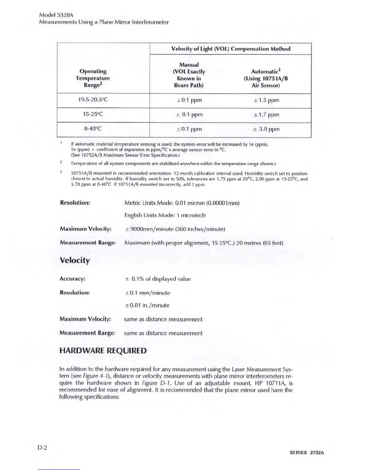
Velocity of
Light
(VOL)
Compensation Method
,
Manual
Operating
(VOL
Exactly
Automa
tic'
Temperature
Known
in
(Using 10151A/B
Range
2
Beam Path)
Air
Sensor)
19.5·20.5
°C
±
0.1
ppm
± 1.5 ppm
lS
-25
Q
C
± 0.1 ppm
±
1.7ppm
0-4O"C
± O.l ppm ± 3.0 ppm
If automatic material temperature sensing
15
used, tile system error will
be
Increased
by
T e (ppm).
Te
(ppm) • coefficient
of
expansion
In
ppm!C
x avera
ge
senior error
In
°e.
(See
10752A/B Maximum SeMor Error Spt!cificatlon.)
Temperature
of
~II
system components
are
stabilized anywhere within the temperature range shown
.)
,
1 0751A/B moonted in recommended orienMtion.
12
month
ca
t
lbl~tion
interval used Humidity switch sci to
po
sition
closest
to
a c
tu~1
humidity. If humidity swit
ch
setta
50%,
tolerances u e 1.75 ppm
at
20
0
e,
2.00 ppm
at
15·25
°e,
and
3.70
ppm
at
0·40"C. If 10751A/B moonted Incorrectly,
~dd
2 ppm.
Resolution: Metric Units Mode:
0.01
micron
(O.OOOOlm
m)
Eng
li
sh U
nit
s Mode: 1 microinch
Maximum Velocity: ± 9000mm/ minute (360 inch
es/m
inut
e)
Measurement
Range: Maximum
(wit
h proper
alig
nm
ent, 15
-2
5
°C.
) 20 metres
(65
feel)
Velocity
Accuracy:
±
0.1% of displayed
va
lu
e
Resolution:
±
O.1
mm/minute
± O
.O
l
in
./
minute
Maximum Velocity: same as distance measurement
Me
asurement
Range:
Silme
ilS
distilnce meilsureme
nt
HARDWARE
REQUIRED
In
addition to the hardware required
for
any measurement using the
laser
Measurement
Sys-
tem (see Figure 4·
1),
distance or velocity measurements with plilne mirror interferometers re-
quire the hardware shown
In
Figure
0 -
1.
Use of
iln
ildjustilble mount,
HP
107
11
A,
is
re
co
mmended
for
ease
of illignment.
It
is recommended thilt the plilne mirror used have
th
e
following specificiltion
s:
SEAlES 2732A