31
IPv6 NTP client/server mode configuration
example
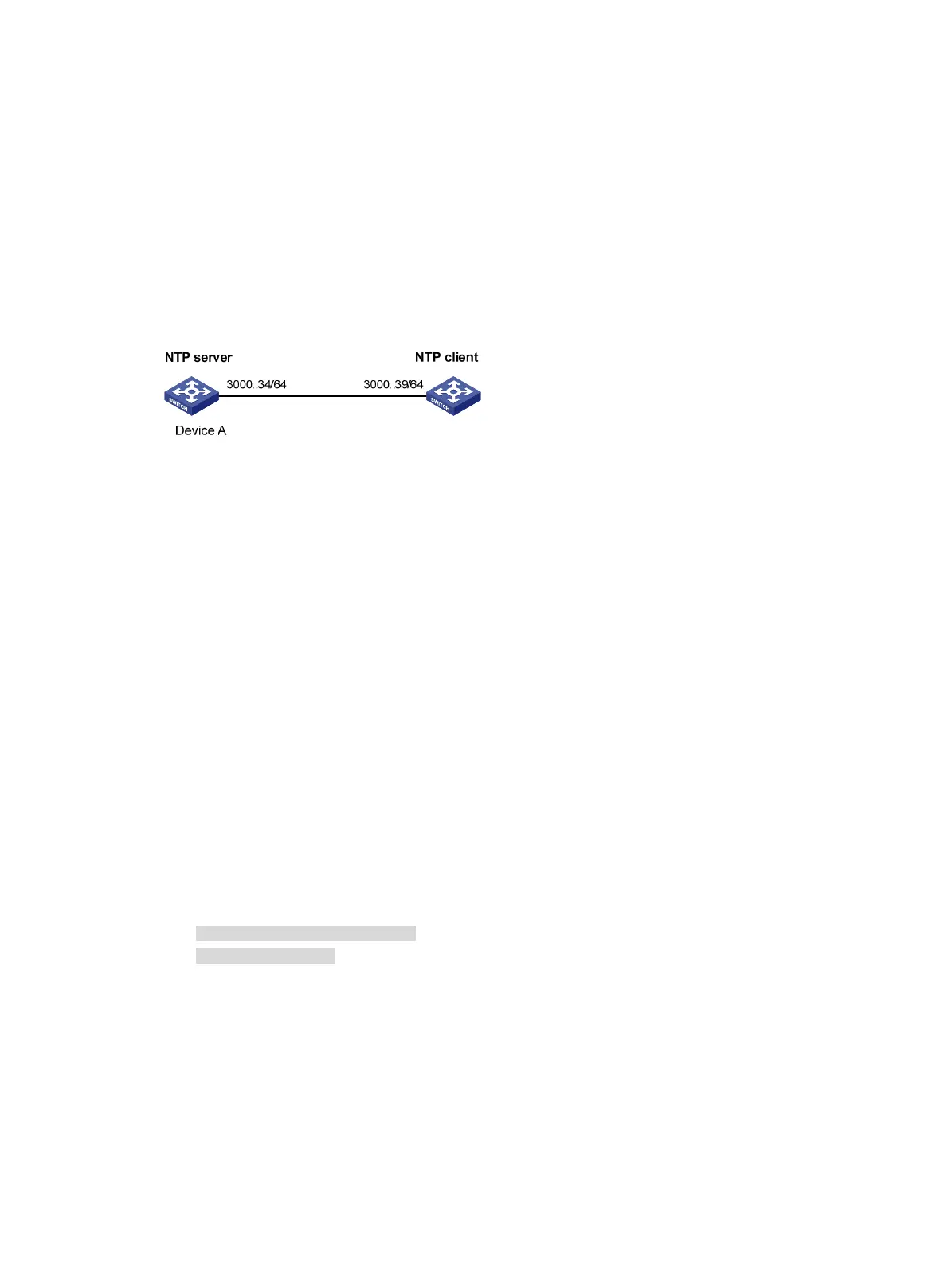
Network requirements
As shown in Figure 10, the local clock of Device A is to be used as a reference source, with the stratum
level 2. Device B operates in client mode and Device A is to be used as the IPv6 NTP server for Device
B.
Figure 10 Network diagram
Configuration procedure
1. Set the IP address for each interface as shown in Figure 10. (Details not shown.)
2. Configure Device A:
# Enable the NTP service.
<DeviceA> system-view
[DeviceA] ntp-service enable
# Specify the local clock as the reference source, with the stratum level 2.
[DeviceA] ntp-service refclock-master 2
3. Configure Device B:
# Enable the NTP service.
<DeviceB> system-view
[DeviceB] ntp-service enable
# Specify Device A as the IPv6 NTP server of Device B so that Device B is synchronized to Device
A.
[DeviceB] ntp-service ipv6 unicast-server 3000::34
4. Verify the configuration:
# Display the NTP status of Device B after clock synchronization.
[DeviceB] display ntp-service status
Clock status: synchronized
Clock stratum: 3
System peer: 3000::34
Local mode: client
Reference clock ID: 163.29.247.19
Leap indicator: 00
Clock jitter: 0.000977 s
Stability: 0.000 pps
Clock precision: 2^-10
Root delay: 0.02649 ms
Root dispersion: 12.24641 ms
Reference time: d0c60419.9952fb3e Wed, Dec 29 2010 19:01:45.598

 Loading...