48
source reference stra reach poll now offset delay disper
********************************************************************************
[1245]3.0.1.31 127.127.1.0 3 3 64 68 -0.0 0.0000 0.0
Notes: 1 source(master),2 source(peer),3 selected,4 candidate,5 configured.
Total sessions : 1
The output shows that an association has been set up between Switch B and Switch C.
Configuration example for MPLS VPN time
synchronization in client/server mode
Network requirements
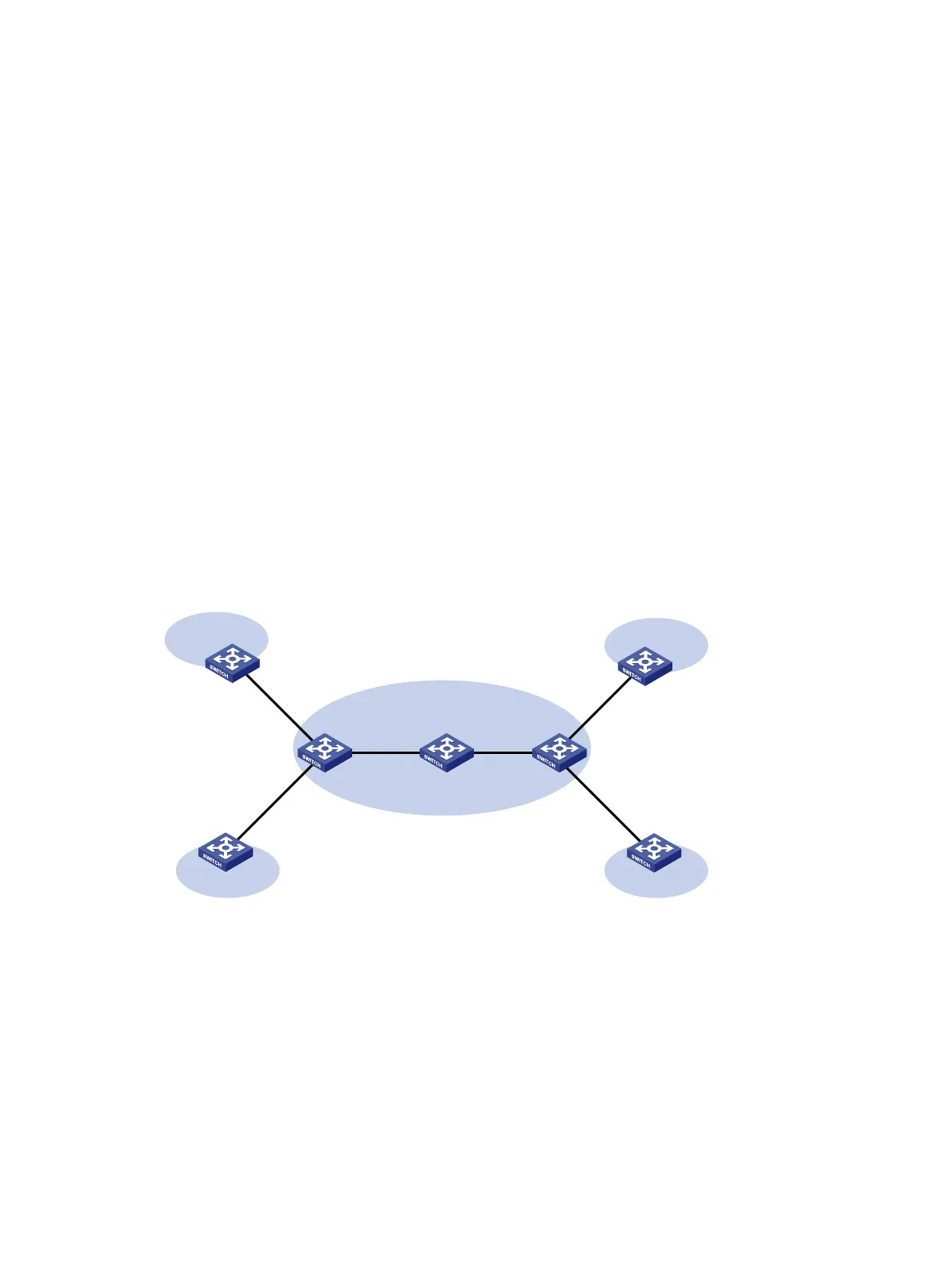
As shown in Figure 18, two VPNs are present on PE 1 and PE 2: VPN 1 and VPN 2. CE 1 and CE 3 are
devices in VPN 1.
To synchronize the time between PE 2 and CE 1 in VPN 1, do the following:
• Configure CE 1's local clock as a reference source, with the stratum level 2.
• Configure PE 1 to operate in client/server mode.
• Specify VPN 1 as the target VPN.
Figure 18 Network diagram
Configuration procedure
Before you perform the following configuration, be sure you have completed MPLS VPN-related
configurations and make sure of the reachability between CE 1 and PE 1, between PE 1 and PE 2, and
between PE 2 and CE 3. For information about configuring MPLS VPN, see MPLS Configuration Guide.
1. Set the IP address for each interface as shown in Figure 18. (Details not shown.)
2. Conf
igure CE 1:
# Enable the NTP service.
<CE1> system-view
[CE1] ntp-service enable
CE 1
NTP server
CE 2 CE 4
CE 3
PE 1
PE 2
NTP client
P
VPN 1
VPN 2
VPN 1
VPN 2
10.1.1.1/24 10.3.1.1/24
10.3.1.2/24
MPLS backbone

 Loading...