15
Figure 11 Attaching the cable management bracket to the left mounting bracket
(1) Left mounting bracket (2) Cable management bracket
(3) Screw hole for installin
Installing mounting brackets
Before installing the switch to the rack, install the mounting brackets to the chassis, as shown in Figure 12.
• 7506-V—Facing the front of the switch, mount the left and right mounting bracket to the two sides
of the switch.
• Other models—Facing the front of the switch, mount the mounting bracket with a cable
management bracket to the left of the switch, and mount the mounting bracket without a cable
management bracket to the right of the switch (where the fan assembly is located).
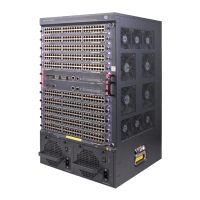
Figure 12 Installing the mounting brackets (7503)
(1) Screws for fixin

 Loading...