Operation Model
8901B
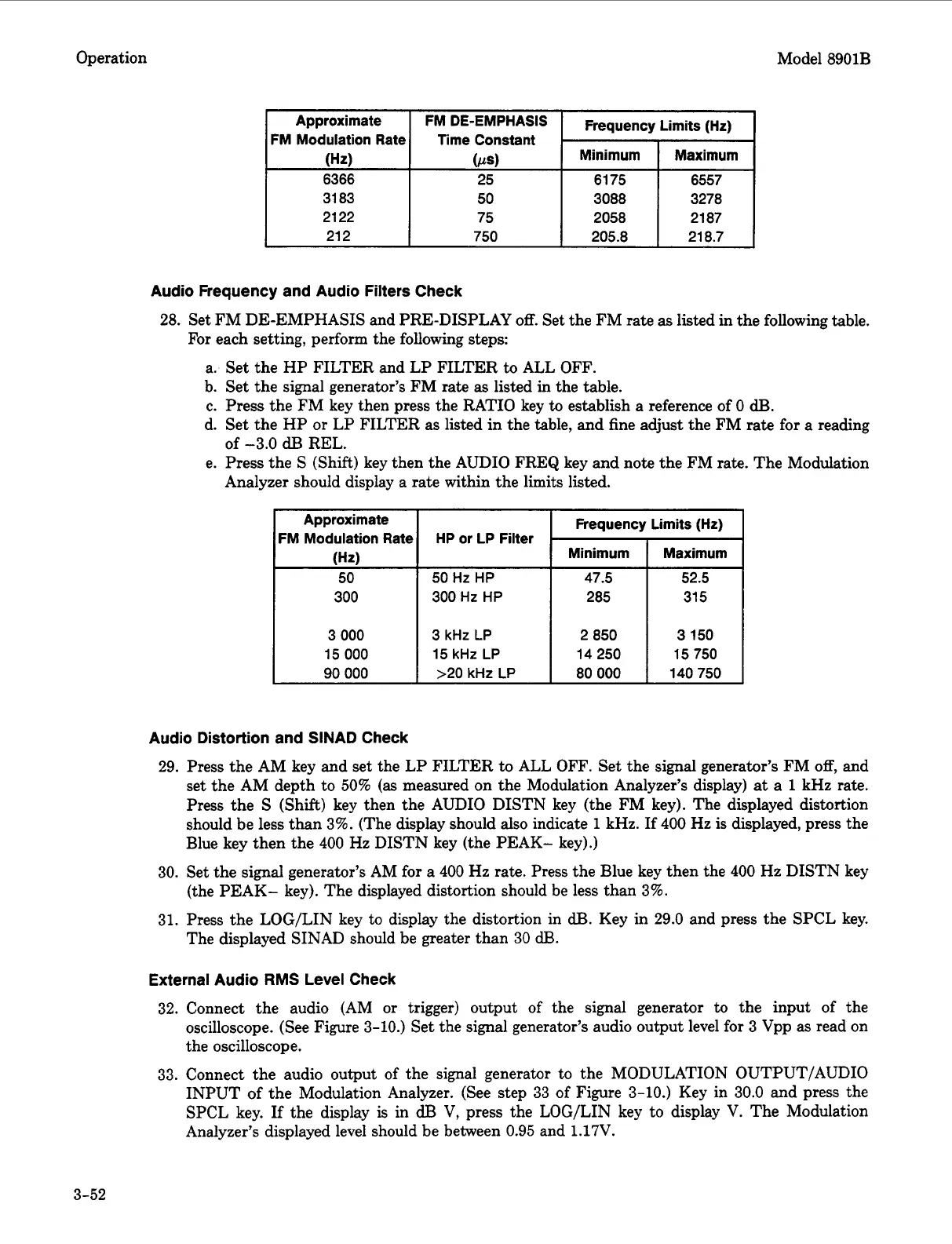
Approximate
FM Modulation Rate
FM
Frequency Limits (Hz)
Time Constant
Minimum Maximum
31 83
3088
21 22 75 2058 21 87
21 2 750 205.8 21 8.7
Approximate
FM Modulation Rate
(Hz)
50
300
Audio Frequency and Audio Filters Check
28.
Set FM DE-EMPHASIS and PRE-DISPLAY
off.
Set the FM rate as listed in the following table.
For each setting, perform the following steps:
a. Set the HP FILTER and LP FILTER
to
ALL OFF.
b. Set the signal generator’s FM rate
as
listed in the table.
c. Press the FM key then press the RATIO key
to
establish a reference of
0
dB.
d. Set the HP
or
LP FILTER as listed in the table,
and
fine adjust the FM rate for
a
reading
e. Press the
S
(Shift) key then the AUDIO FREQ key and note the FM rate. The Modulation
of
-3.0
dB
REL.
Analyzer should display a rate within the limits listed.
Frequency Limits (Hz)
Minimum Maximum
HP or LP Filter
50
Hz
HP
47.5 52.5
300 Hz
HP
285 31
5
3
000
15
000
90
000
3
kHz
LP
2 850 3
150
15 kHz
LP
1
14250
1
15750
>20 kHz
LP
80
000
140 750
Audio Distortion and SINAD Check
29.
Press the AM key and set the LP FILTER to ALL OFF. Set the signal generator’s FM
off,
and
set the AM depth to
50%
(as
measured on the Modulation Analyzer’s display)
at
a
1
kHz rate.
Press the
S
(Shift) key then the AUDIO DISTN key (the FM key). The displayed distortion
should be less than
3%.
(The display should also indicate
1
kHz. If
400
Hz is displayed, press the
Blue key then the
400
Hz DISTN key (the PEAK- key).)
30.
Set the signal generator’s AM for
a
400
Hz
rate. Press the Blue key then the
400
Hz DISTN key
(the PEAK- key). The displayed distortion should be less than
3%.
31.
Press the LOG/LIN key
to
display the distortion in
dB.
Key in
29.0
and press the SPCL key.
The displayed SINAD should be greater than
30
dEL
External Audio
RMS
Level
Check
32.
Connect the audio (AM
or
trigger) output
of
the signal generator to the input of the
oscilloscope. (See Figure
3-10.)
Set the signal generator’s audio output level for
3
Vpp as read on
the oscilloscope.
33.
Connect the audio output
of
the signal generator to the MODULATION OUTPUT/AUDIO
INPUT of the Modulation Analyzer. (See step
33
of
Figure
3-10.)
Key in
30.0
and press the
SPCL key. If the display is in
dl3
V, press the LOG/LIN key to display V. The Modulation
Analyzer’s displayed level should be between
0.95
and
1.17V.
3-52

 Loading...


