Operation
Model
8901B
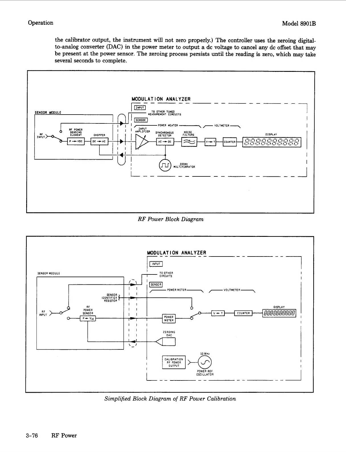
the calibrator output, the instrument will not zero properly.) The controller uses the zeroing digital-
to-analog converter
(DAC)
in the power meter to output
a
dc voltage
to
cancel any dc offset that may
be present
at
the power sensor. The zeroing process persists until the reading
is
zero, which may take
several seconds to complete.
MODULATION ANALYZER
1
------------__
TO
OTHER TUNED
rm
MEASUREMENT CIRCUITS
;ENSOR
MODULE
,
I
I
I
..
INPUT
RF
ELEMENT CHOPPER DETECTOR DISPLAY
RF
POWER
SENSING
INPUI
RF
Power
Block
Diagram
-7
--
MODULATION ANALYZER
--
SENSOR MOOULE
r
TO
--
OTHER
I
1-
CIRCUITS
,
-a
'm
I
'
,-POWERMETER-,
7
VOLTMETER-
SENSOR
I
I
RESISTOP
-
I
II
II
II
I1
I
IOENTIFIER
DISPLAY
rtl
I
I
RF
INPUT
J
I
El&@
CALIBRATION
POWER
REF
OSCILLATOR
Simplified
Block
Diagram
of
RF
Power
Calibration
3-76
RF
Power

 Loading...


