Model 8901B Operation
When CALIBRATE is selected, the power reference oscillator outputs a calibrated,
1
mW signal at
50
MHz. When SAVE CAL is selected, the controller equates the output from the power meter to
1
mW.
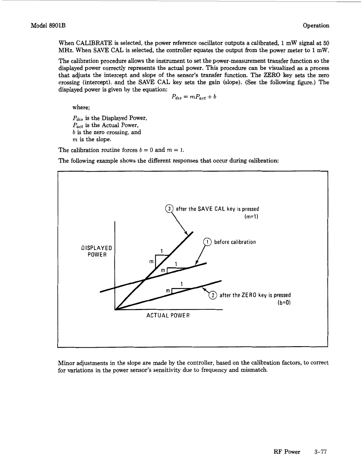
The calibration procedure allows the instrument to set the power-measurement transfer function
so
the
displayed power correctly represents the actual power. This procedure can be visualized as a process
that adjusts the intercept and slope of the sensor’s transfer function. The ZERO key sets the zero
crossing (intercept), and the SAVE CAL key sets the gain (slope). (See the following figure.) The
displayed power is given by the equation:
Pdi3
=
mPact
+
b
where;
Pdi3
is
the Displayed Power,
Pact
is
the Actual Power,
b
is
the zero crossing, and
m
is the slope.
The calibration routine forces
b
=
0
and
m
=
1.
The following example shows the different responses that occur during calibration:
DISPLAYED
POWER
the
SAVE CAL
key
is
pressed
(rn=l)
ACTUAL POWER
Minor adjustments in the slope are made by the controller, based on the calibration factors, to correct
for variations in the power sensor’s sensitivity due to frequency and mismatch.
RF Power
3-77

 Loading...


