Operation
Model
8901B
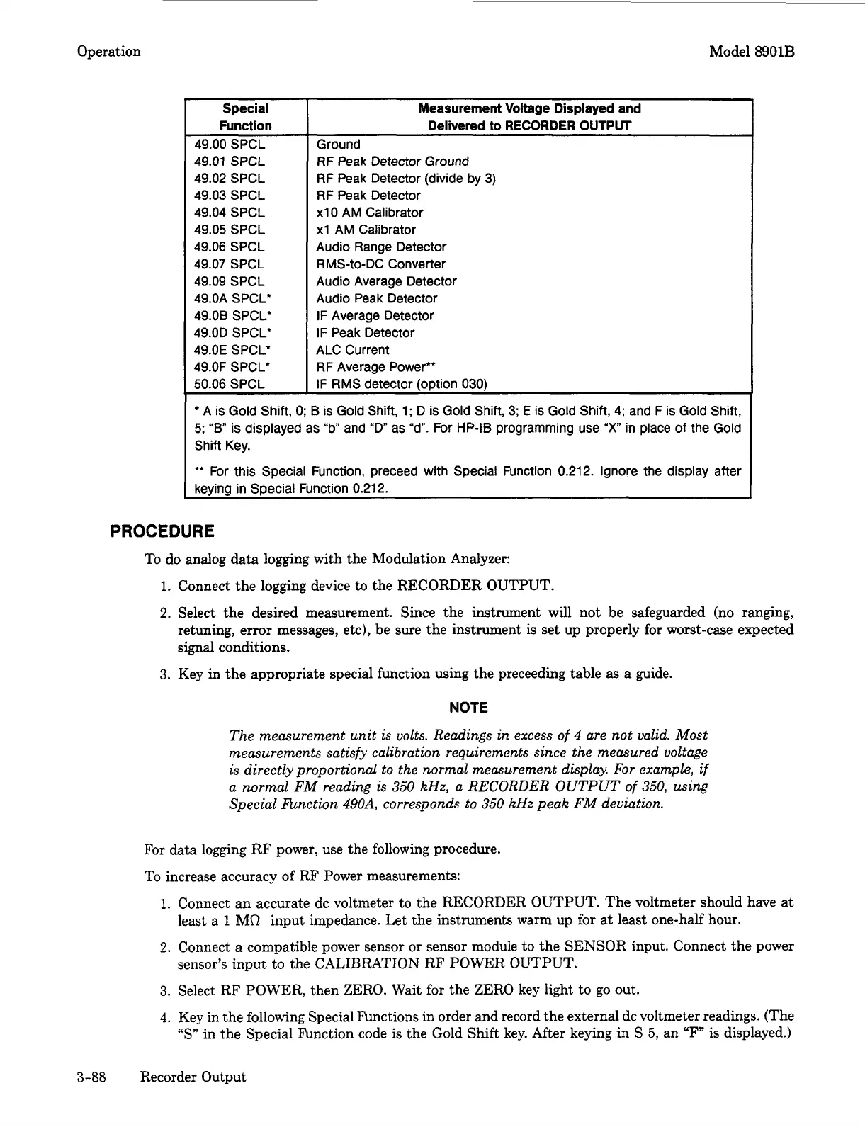
Special
Function
49.00 SPCL
49.01 SPCL
49.02 SPCL
49.03 SPCL
49.04 SPCL
49.05 SPCL
49.06 SPCL
49.07 SPCL
49.09 SPCL
49.OA SPCL’
49.08 SPCL’
49.OD SPCL‘
49.OE SPCL*
49.0F SPCL*
50.06 SPCL
~~
Measurement Voltage Displayed and
Delivered to
RECORDER
OUTPUT
Ground
RF
Peak Detector Ground
RF Peak Detector (divide by 3)
RF Peak Detector
xl0
AM Calibrator
xl
AM Calibrator
Audio Range Detector
RMS-to-DC Converter
Audio Average Detector
Audio Peak Detector
IF Average Detector
IF
Peak Detector
ALC Current
RF
Average Power”
IF RMS detector (oDtion
030)
A
is Gold Shift, 0;
B
is Gold Shift,
1;
D is Gold Shift,
3;
E
is Gold Shift, 4; and F is Gold Shift,
5;
“8”
is
displayed as
“b
and
“D”
as “d”. For HP-IB programming use
“X
in
place
of
the Gold
Shift Key.
** For this Special Function, preceed with Special Function 0.212. Ignore the display after
keying in Special Function 0.212.
PROCEDURE
To
do
analog data logging with the Modulation Analyzer:
1.
Connect the logging device
to
the RECORDER OUTPUT.
2.
Select the desired measurement. Since the instrument will not be safeguarded (no ranging,
retuning,
error
messages, etc), be sure the instrument
is
set up properly for worst-case expected
signal conditions.
3.
Key in the appropriate special function using the preceeding table
as
a guide.
NOTE
The measurement unit is volts. Readings in excess
of
4
are not valid. Most
measurements satisfy calibration requirements since the measured voltage
is directly proportional to the normal measurement display. For example, if
a normal
FM
reading is
350
kHz, a RECORDER OUTPUT
of
350,
using
Special hnction
490A,
corresponds to
350
kHz peak FM deviation.
For
data logging RF power, use the following procedure.
To increase accuracy
of
RF Power measurements:
1.
Connect an accurate de voltmeter to the RECORDER OUTPUT. The voltmeter should have at
least a
1
MR
input impedance. Let the instruments warm up for at least one-half hour.
sensor’s input to the CALIBRATION RF POWER OUTPUT.
2.
Connect a compatible power sensor
or
sensor module to the SENSOR input. Connect the power
3.
Select RF POWER, then ZERO. Wait for the ZERO key light to go out.
4.
Key in the following Special Functions in order and record the external dc voltmeter readings. (The
“S”
in the Special hnction code
is
the Gold Shift key. After keying in
S
5,
an
“F”
is displayed.)
3-88
Recorder Output

 Loading...


