Model
8901B
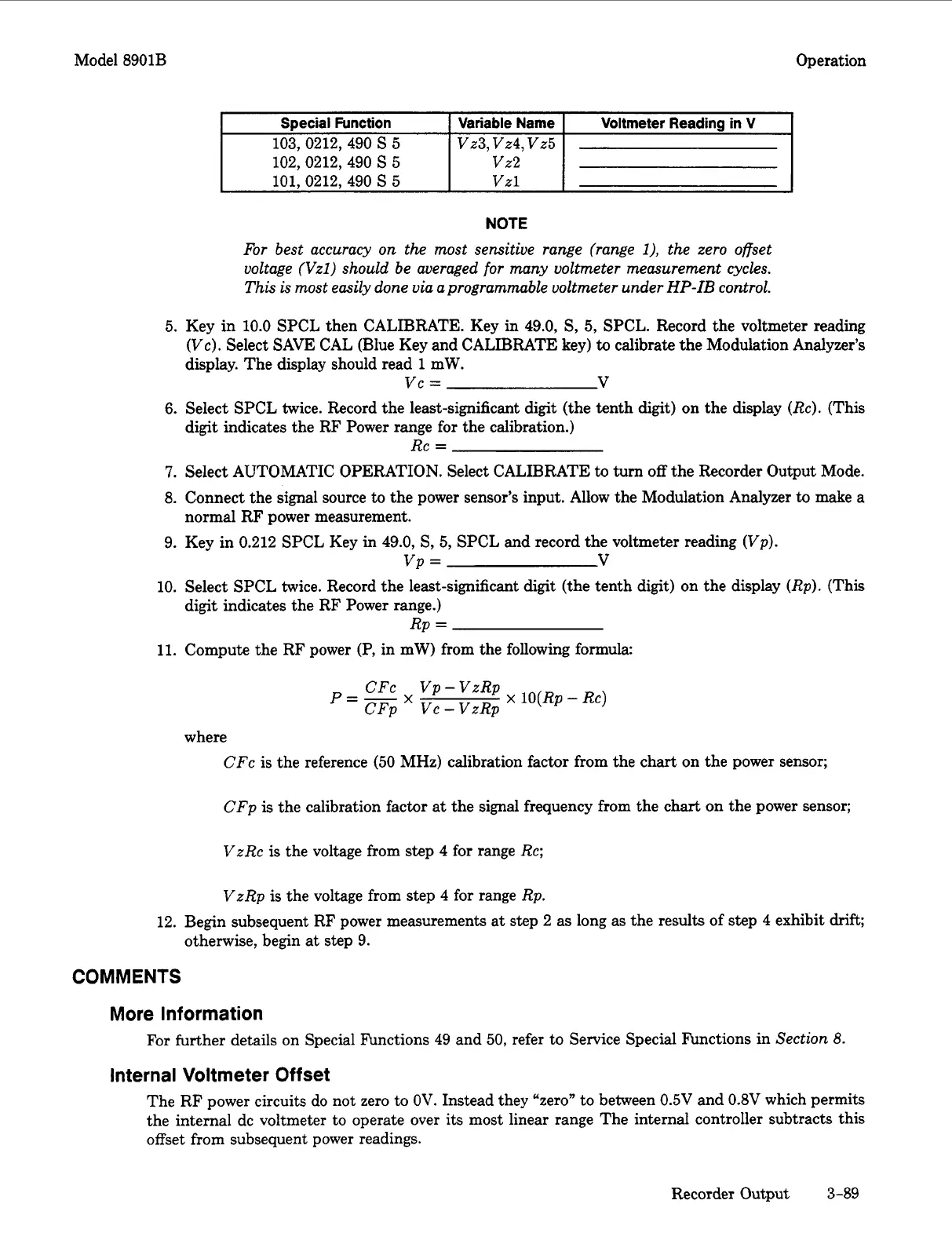
Special Function
103,0212, 490
S
5
102,0212,490
S
5
101.0212.490
S
5
Operation
Variable Name
vz3, vz4,
vz5
vz2
Vzl
Voltmeter Reading in V
5.
6.
7.
8.
9.
10.
11.
12.
NOTE
For
best
accuracy
on the most sensitive range (range
I),
the zero offset
voltage (Vzl) should be averaged
for
many voltmeter measurement cycles.
This
is
most easily done via aprogrammable voltmeter under
HP-IB
control.
Key in 10.0 SPCL then CALIBRATE. Key in 49.0,
S,
5, SPCL. Record the voltmeter reading
(Vc). Select SAVE CAL (Blue Key and CALIBRATE key)
to
calibrate the Modulation Analyzer’s
display. The display should read
1
mW.
Select SPCL twice. Record the least-significant digit (the tenth digit) on the display (Re). (This
digit indicates the RF Power range for the calibration.)
Select AUTOMATIC OPERATION. Select CALIBRATE
to
turn
off
the Recorder Output Mode.
Connect the signal source
to
the power sensor’s input. Allow the Modulation Analyzer to make a
normal RF power measurement.
Key in 0.212 SPCL Key
in
49.0,
S,
5, SPCL and record the voltmeter reading (Vp).
Select SPCL twice. Record the least-significant digit (the tenth digit) on the display (Rp). (This
digit indicates the RF Power range.)
Compute the RF power
(P,
in mW) from the following formula:
vc
=
V
Rc
=
vp
=
V
Rp
=
CFC Vp-VzRp
CFp VC-VzRp
p=-
X
x
10(Rp
-
Rc)
where
CFc is the reference (50 MHz) calibration factor from the chart on the power sensor;
CFp
is
the calibration factor
at
the signal frequency from the chart on the power sensor;
VzRc
is
the voltage from step 4 for range Rc;
VzRp is the voltage from step 4 for range Rp.
Begin subsequent RF power measurements at step 2 as long as the results of step 4 exhibit
drift;
otherwise, begin at step
9.
COMMENTS
More Information
Internal Voltmeter Offset
For
further details on Special Functions 49 and
50,
refer to Service Special finctions in
Section
8.
The RF power circuits do not zero to
OV.
Instead they “zero” to between 0.5V and
0.8V
which permits
the internal dc voltmeter to operate over its most linear range The internal controller subtracts this
offset
from subsequent power readings.
Recorder Output
3-89

 Loading...


