Model
8901B
>-
H-
-
c’>c/
Operation
Tuned
RF
Level
FUNCTIONS
TUNED RF LEVEL
DESCRl PTl ON
The Tuned RF Level function enables the Modulation Analyzer
to
measure the peak level of the down-
converted RF input falling in the IF. The term “peak level” refers
to
the fact that a peak-responding IF
detector is used
to
measure the signal level. The internal controller converts this level
to
average power
and displays the result. (See the block diagram in “MEASUREMENT TECHNIQUE”.) The Tuned
RF Level function is not calibrated, and
so
it
is
not
as
accurate
or
sensitive
as
the
RF
Power function.
The peak Tuned RF Level function enables the instrument
to
measure the level of frequencies that
are
drifting,
or
to
determine flatness as
a
function of carrier frequency. This function
is
more sensitive
than the RF Level (Special Function
35)
measurement mode.
PROCEDURE
To make
a
tuned RF level measurement, first tune the instrument to the input signal by selecting
AUTOMATIC OPERATION. Select TUNED RF LEVEL (Shift, RF POWER).
HP-IB PROGRAM CODES
LIN results
=
LN
LOG results
=
LG
VOLTS units
=
VL
mV units
=
MV
uV units
=
UV
WATTS units
=
WT
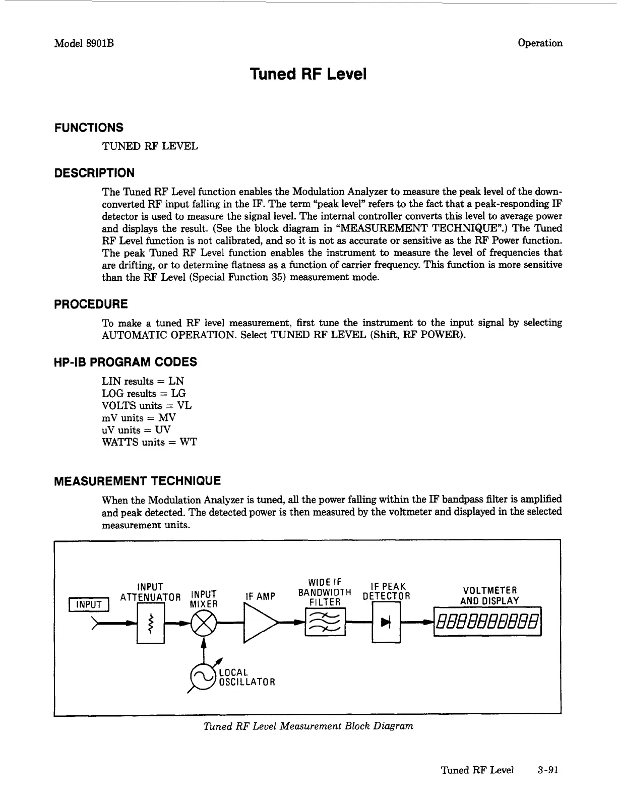
MEASUREMENT TECHNIQUE
When the Modulation Analyzer is tuned, all the power falling within the IF bandpass filter
is
amplified
and peak detected. The detected power is then measured by the voltmeter and displayed in the selected
measurement units.
I
lbned
RF
Level Measurement
Block
Diagram
Timed RF Level
3-91

 Loading...


